Annular Ion Guide

a technology of annular ions and guides, applied in the direction of mass spectrometers, stability-of-path spectrometers, separation processes, etc., can solve the problems of significant disruption of the electric field, become difficult to apply transient dc or travelling dc voltage waves to such devices, and achieve increased charge capacity, large ions population, and high charge capacity

Active Publication Date: 2015-02-19
MICROMASS UK LTD
View PDF4 Cites 10 Cited by
  • Summary
  • Abstract
  • Description
  • Claims
  • Application Information

AI Technical Summary

Benefits of technology

[0086]The present invention results in an ion guide or ion trap having an increased charge capacity thereby allowing larger populations of ions to be handled without degrading performance. This increases the dynamic range of the preferred ion guide or ion trap.
[0087]The present invention provides a high charge capacity ion guide or ion trap and therefore allows the transport or separation of large populations of ions with less distortion due to space charge interaction than conventional ion guides.

Problems solved by technology

However, it becomes progressively harder to apply a transient DC or travelling DC voltage wave to such a device in order to urge ions along the length of the on guide due to the fact that the electric field relaxes within the ion guide.
However, this can become problematic.
If it is required to apply a linear or non linear DC electric field over the axial length of the ion guide, then electric field penetration or relaxation at the entrance and exit of the device can cause significant disruption of the electric field.
However, such ion guides suffer from the problem that electric field effects at the extremes of the device in the radial direction of elongation prevent ions from occupying the entire internal volume.
The limited space charge capacity of conventional ion traps and ion guides can result ire loss of transmission or sensitivity due to inefficient ion confinement which leads to ion losses.
Furthermore, conventional ion traps and ion guides may suffer from loss of analytical performance when used as an ion mobility separator (“IMS”) or mass to charge ratio separator.
This is characterised by loss of resolution or separation power and / or by unexpected shifts in on ejection times. These shifts lead to inaccuracy of analytical measurements.

Method used


Image

  • Annular Ion Guide
  • Annular Ion Guide
  • Annular Ion Guide

Examples


Embodiment Construction

[0113]A conventional stacked ring on guide will first be described.

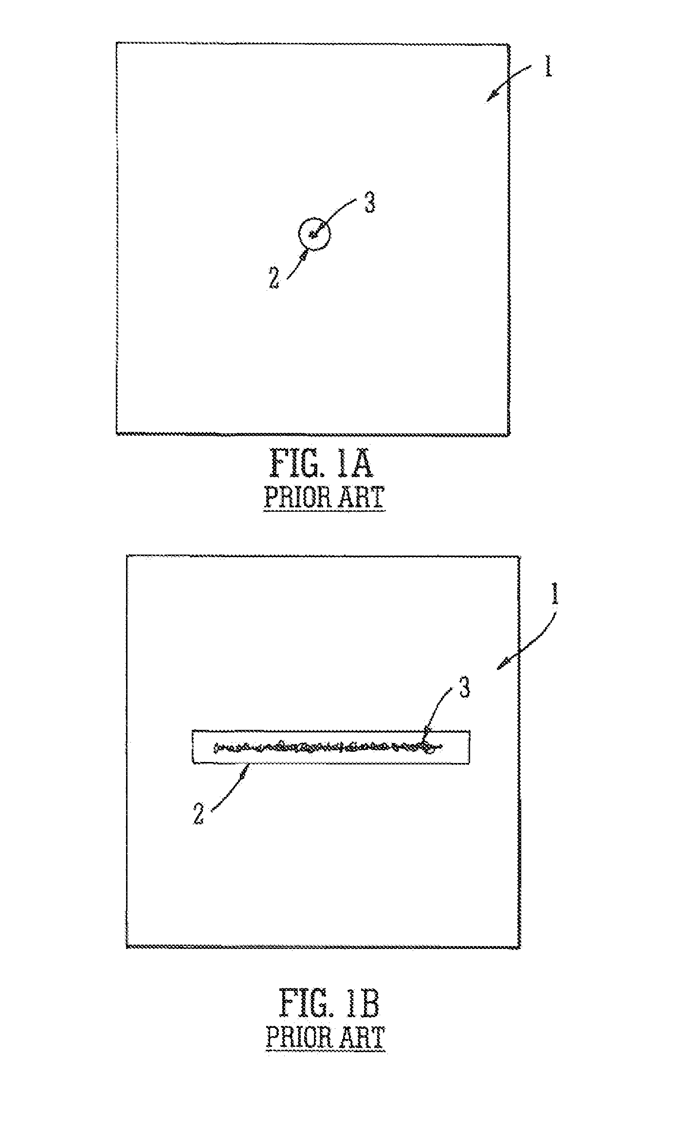
[0114]FIG. 1A shows an electrode 1 of a conventional stacked ring ion guide in the (x, y) plane. Each electrode 1 has a circular hole or aperture 2 which defines an ion trapping region in the radial (x, y) direction. An ion cloud 3 may be confined within this region and will extend the axial (z) direction. The conventional stacked ring ion guide comprises a series of electrodes 1 wherein axially adjacent electrodes are supplied with opposite phases of an RF voltage.

[0115]FIG. 1B shows another known stacked ring on guide in the (x, y) plane. According to this arrangement the opening or aperture 2 in each plate electrode 1 is elongated in one axis. Ions 3 may take up positions as shown in the (x, y) plane. It is apparent that the volume occupied by ions in the arrangement shown in FIG. 1B is greater than the volume occupied by ions in the arrangement shown in FIG. 1A.

[0116]However, as shown in FIG. 1B, ions cannot occu...


PUM


Abstract

An annular ion guide is disclosed comprising inner and outer electrodes. Ions are confined within an annular ion guiding region by RF or pseudo-potential barriers in both an outward and inward radial direction.

Description

CROSS-REFERENCE TO RELATED APPLICATION[0001]This application claims priority from and the benefit of U.S. Provisional Patent Application Ser. No. 61 / 547,210 filed on 14 Oct. 2011 and United Kingdom Patent Application No. 1117158.4 filed on 5 Oct. 2011. The entire contents of these applications are incorporated herein by reference.[0002]The present invention relates to an ion guide or ion trap, a mass spectrometer, a method of guiding ions and a method of mass spectrometry.BACKGROUND TO THE PRESENT INVENTION[0003]Stacked ring ion guides are well known and comprise a plurality of ring electrodes each having an aperture through which ions are transmitted. The ion confining region of conventional stacked ring ion guides is circular in cross section.[0004]It is known to increase the capacity of a conventional stacked ring ion guide by increasing the radius of the aperture to allow ions to occupy a larger volume. However, it becomes progressively harder to apply a transient DC or travelli...

Claims


Application Information

Patent Timeline
Patent Type & Authority Applications(United States)
IPC IPC(8): H01J49/42H01J49/36
CPCH01J49/36H01J49/424H01J49/065H01J49/066H01J49/062H01J49/422
Inventor GREEN, MARTIN RAYMONDLANDRIDGE, DAVID J.
Owner MICROMASS UK LTD
Why Eureka
Try Eureka