Surgical retractor system and methods of use

a retractor and surgical technology, applied in the field of surgical retractors, can solve the problems of muscle trauma, further stretching or compressing nerve roots in the surrounding tissue,

Active Publication Date: 2015-02-19
SPINAL HUNT LLC +1
View PDF3 Cites 25 Cited by
  • Summary
  • Abstract
  • Description
  • Claims
  • Application Information

AI Technical Summary

Benefits of technology

[0003]In one aspect, the technology relates to surgical retractors and methods of use. In one embodiment, a surgical retractor includes an elongate element defining as operational axis. A first blade, having a first blade face, is secured to the elongate element. A second blade defining an opening is moveably secured to the elongate element and defines a reference point thereon. Movement of the second blade moves the reference point in a linear direction generally parallel to the operational axis and generally orthogonal to the blade face. A guide element is removably received within the opening.

Problems solved by technology

These round dilators, coupled with multi-blade retractors that spread radially, can cause muscular trauma, and can further stretch or compress nerve roots in the surrounding tissue.

Method used


Image

  • Surgical retractor system and methods of use
  • Surgical retractor system and methods of use
  • Surgical retractor system and methods of use

Examples


Embodiment Construction

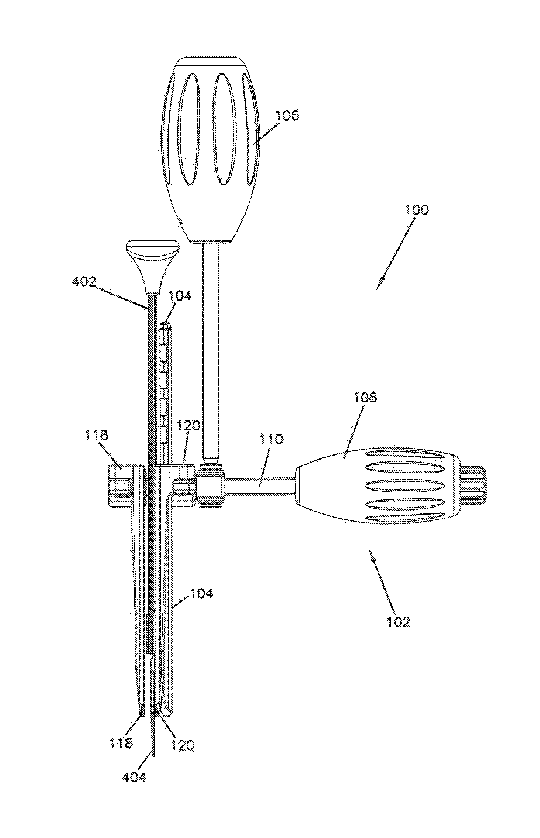
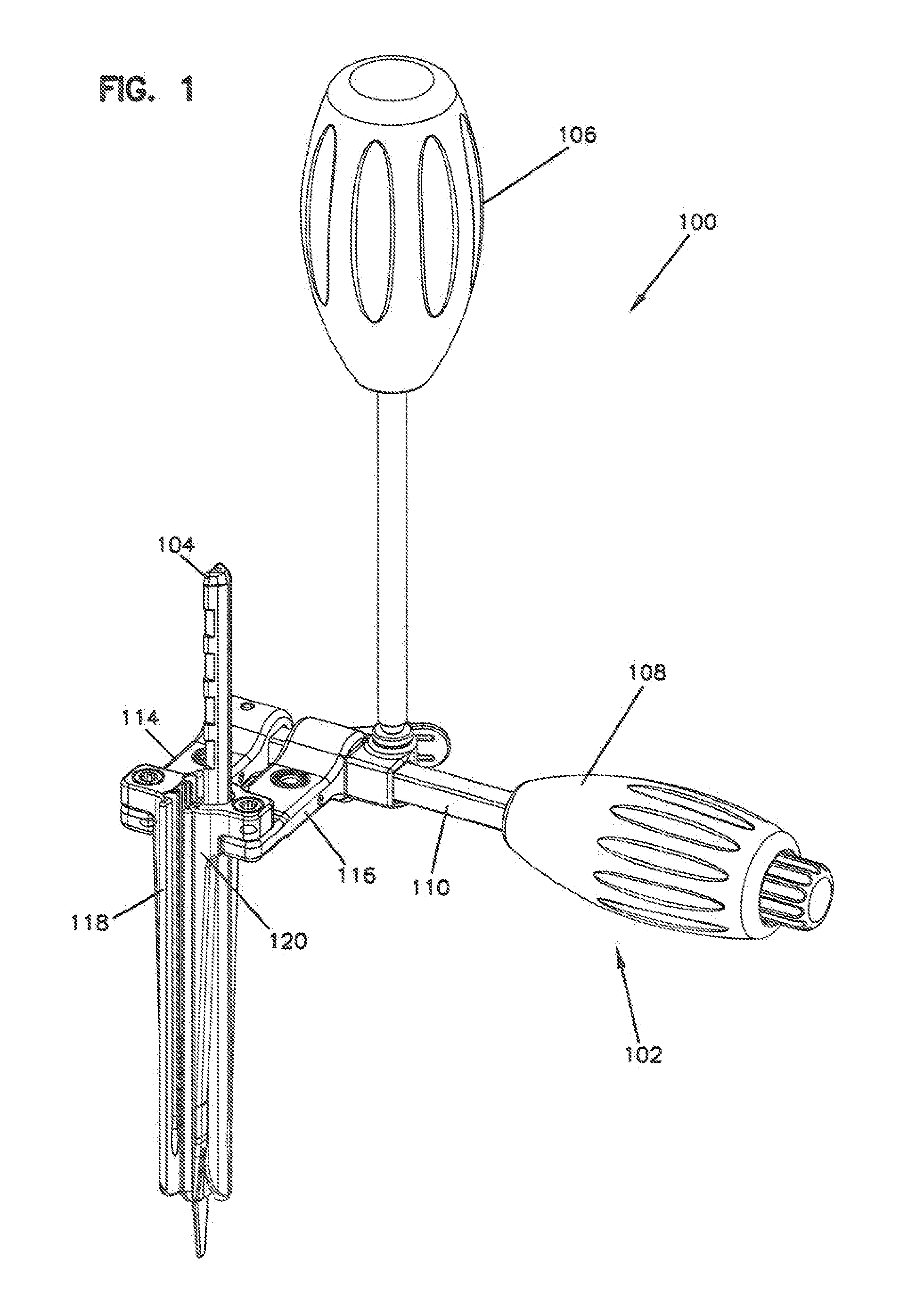
[0014]FIG. 1 depicts a retractor system 100 that includes, generally, a retractor device 102, a guide element 104, and a driver 106. The retractor device 102 includes a handle 108 coupled to an elongate element 110 to which two blades 118, 120 are secured. In some embodiments, the handle 108 is a removable handle that is selectively coupled to or removed from the elongate element 110. The blades 118, 120 may be secured directly to the elongate element 110 or secured with one or more armatures 114, 116. As shown in FIG. 1, in one embodiment, the armatures 114, 116 extend from a side of the elongate element 110, such that a surgical opening created by the blades 118, 120 may be accessible by the surgeon performing the operation without obstruction by the elongate element 110. One or both of the armatures 114, 116 may be moveably secured to the elongate element 110. In this particular embodiment, the driver 106 is used to actuate a moving mechanism, in this case, to rotate a gear that ...


PUM


Abstract

The present disclosure describes a surgical retractor system and method. The surgical retractor includes an elongate element defining an operational axis, a first blade secured to the elongate element and comprising a blade face, a second blade moveably secured to the elongate element, wherein the second blade defines a reference point located thereon, and wherein a movement of the second blade moves the reference point in a linear direction parallel to the operational axis and orthogonal to the blade face. A guide element may be removably located within an opening located on either the first blade or the second blade.

Description

CROSS-REFERENCE TO RELATED APPLICATIONS[0001]This application claims priority to and the benefit of International Application No. PCT / US2012 / 051480 which was filed on Aug. 17, 2012 claiming priority to and benefit of U.S. Provisional Application Ser. No. 61 / 525,646 filed Aug. 19, 2011, entitled “Surgical Retractor System and Methods of Use”, and U.S. Provisional Application Ser. No. 61 / 532,751, filed Sep. 9, 2011, entitled “Surgical Retractor System and Methods of Use”, the disclosures of which are hereby incorporated by reference herein in their entireties.BACKGROUND[0002]Current retractor systems for lateral spine surgical procedures create a round opening through the psoas muscle, which includes muscle fibers running mostly in the cranial-caudal direction. These systems sequentially inserted round dilators which dilate the surgical site radially away the initial dilator / K-wire insertion point, which can lead to compression of nerves and blood supply on the transverse process of t...

Claims


Application Information

Patent Timeline
Patent Type & Authority Applications(United States)
IPC IPC(8): A61B17/02
CPCA61B17/025A61B2017/0256A61B17/0206A61B17/282A61B2017/00915A61B2017/0092F04C2270/0421
Inventor HUNT, LEONEL A.HUNT, GABRIEL E.SCHIFLE, DREWCAUSEY, GREGBURKHOLDER, ALAN
Owner SPINAL HUNT LLC
Why Eureka
Try Eureka