Supercharge Your Innovation With Domain-Expert AI Agents!

Method of setting and maintaining a tool in a set position for a period of time

Active Publication Date: 2015-02-26
BAKER HUGHES INC
View PDF1 Cites 10 Cited by
  • Summary
  • Abstract
  • Description
  • Claims
  • Application Information

AI Technical Summary

Benefits of technology

This patent describes a way to hold a tool in a specific position for a while. It involves moving a part of a device, getting it to fit into a specific position, and then holding it there. When the tool needs to be removed, the device is designed to quickly and easily dissolve the holding features. The technical effect is a more secure and easy-to-use method for keeping tools in specific positions.

Problems solved by technology

Though these devices work well for the purpose for which they were designed, the process for disengaging set tools and the devices that maintain the tools in the set position once the tools are no longer needed can be costly in both time and money.
In some cases, this might require an additional dedicated run in the hole with attendant delays and monetary costs.

Method used


Image

  • Method of setting and maintaining a tool in a set position for a period of time
  • Method of setting and maintaining a tool in a set position for a period of time

Examples


Embodiment Construction

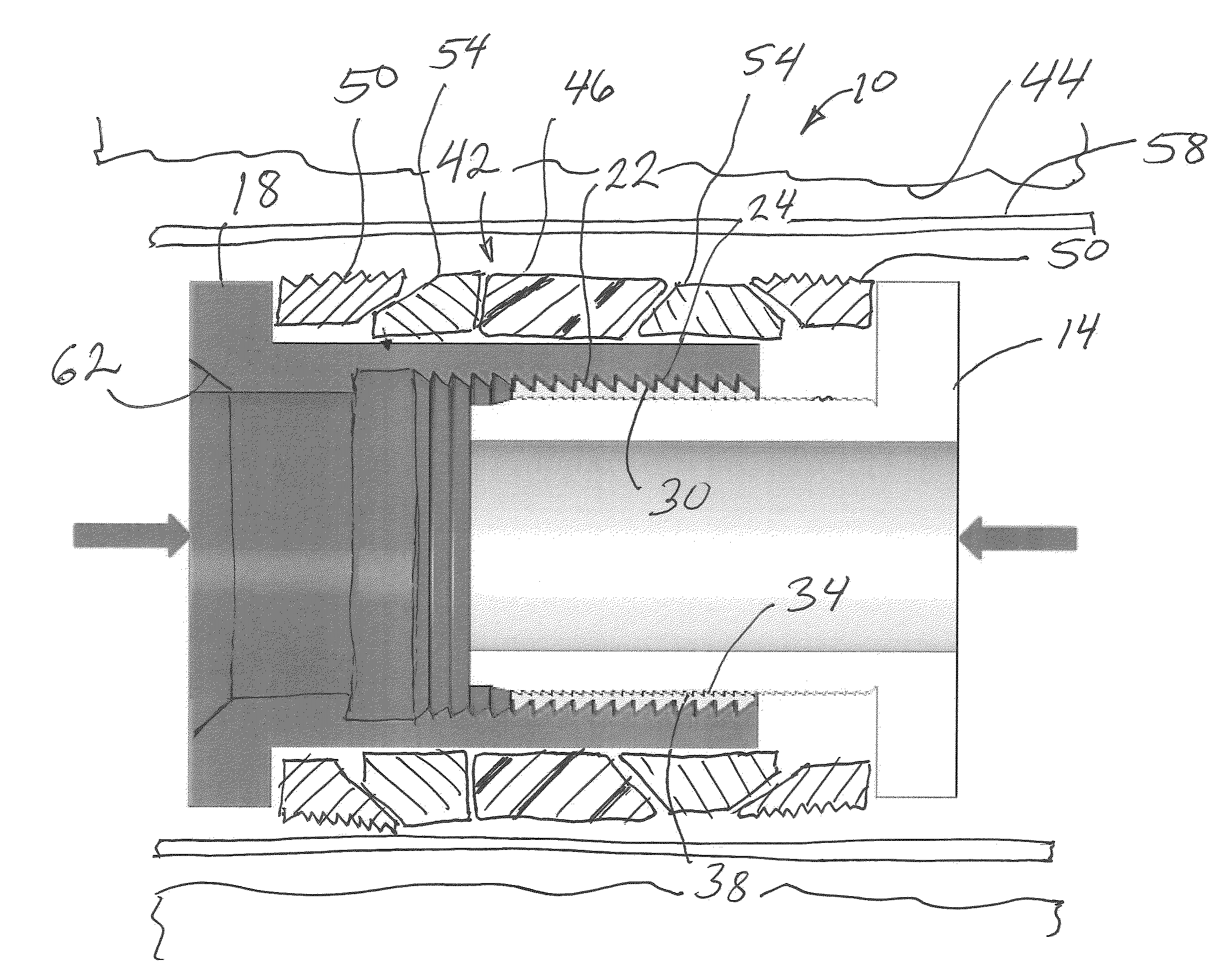
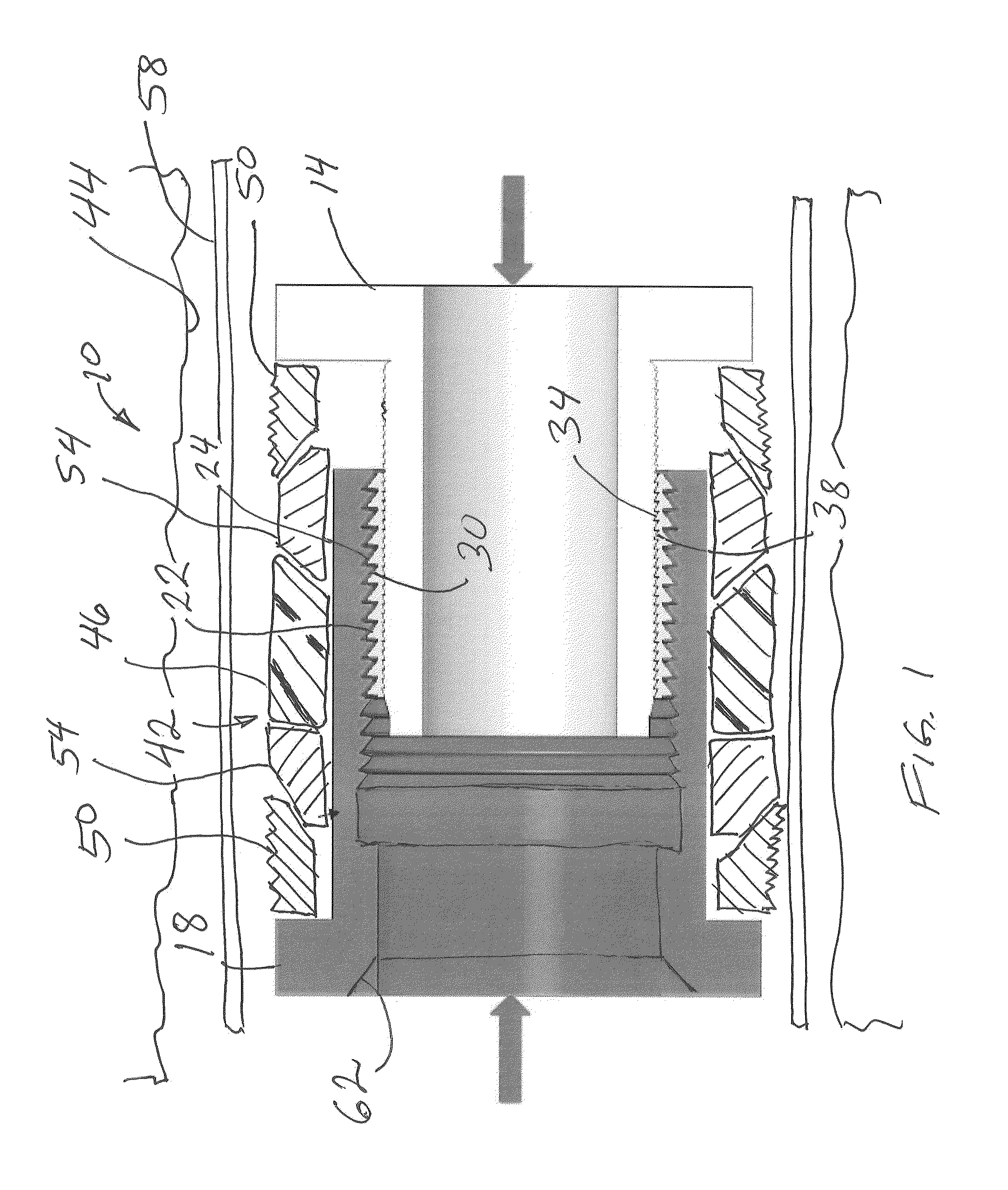
[0005]A detailed description of one or more embodiments of the disclosed apparatus and method are presented herein by way of exemplification and not limitation with reference to the Figures.

[0006]Referring to FIG. 1 a portion of one embodiment of a setting device is illustrated at 10. The portion of the setting device 10 includes at least a first component illustrated herein as a mandrel 14, a second component illustrated herein as a housing 18 and a third component illustrated herein as a body lock ring 22. All three of the components 14, 18 and 22 include features 24, 30, 34 and 38 that are interengagable with one another to allow relative movement of at least the mandrel 14 relative to the housing 18 in a first direction while preventing movement in an opposing direction. In this embodiments the features 24, 30, 34 and 38 are teeth. Specifically, the body lock ring 22 has the teeth 24 that face radially outwardly and engage with the teeth 30 that face radially inwardly on the hou...


PUM


Abstract

A method of setting and maintaining a tool in a set position for a period of time includes the following. Causing a component of a device to move relative to another component of the device, interengaging one or more features of at least one of the components with the another component, creating a set condition of a tool engaged with the component and the another component with the causing and interengaging. The method further includes dissolving at least the one or more features when removal of the tool is desired.

Description

BACKGROUND[0001]Devices have been available for some time for setting a tool within a tubular such as in the downhole hydrocarbon and carbon sequestration industries. Likewise, there are devices for maintaining a tool in the set position. Though these devices work well for the purpose for which they were designed, the process for disengaging set tools and the devices that maintain the tools in the set position once the tools are no longer needed can be costly in both time and money. Disengagement of such devices from the respective tools can in some cases require running a shifting tool or a cutting tool to the device before it can be disengaged. In some cases, this might require an additional dedicated run in the hole with attendant delays and monetary costs. Those who practice in the art will therefore be receptive to methods that overcome the foregoing drawbacks.BRIEF DESCRIPTION[0002]Disclosed herein is a method of setting and maintaining a tool in a set position for a period of...

Claims


Application Information

Patent Timeline
IPC IPC(8): E21B23/06E21B33/12
CPCE21B33/12E21B23/06E21B33/1293E21B33/128
Inventor XU, YINGQINGXU, ZHIYUE
Owner BAKER HUGHES INC
Features
  • R&D
  • Intellectual Property
  • Life Sciences
  • Materials
  • Tech Scout
  • Unparalleled Data Quality
  • Higher Quality Content
  • 60% Fewer Hallucinations
Learn More