Connector

Active Publication Date: 2015-03-05
IRISO ELECTRONICS CO LTD
View PDF1 Cites 22 Cited by
  • Summary
  • Abstract
  • Description
  • Claims
  • Application Information

AI Technical Summary

Benefits of technology

The invention is a connector unit that allows terminals in two connectors to easily deform and make contact with each other. The connectors have movable parts that can be deformed in both the front-back direction and the width direction of the connector. This design increases the cross-sectional area of the terminals, which allows them to handle larger amounts of current. The terminals also have multiple contact points that improve the reliability of the connection, even when exposed to vibration. The invention is useful for large-current devices. Overall, the invention allows for reliable and high-current connections in a simple and easy-to-use connector unit.

Problems solved by technology

Such a configuration impedes an increase in allowable current of the terminal, thus making it difficult to employ the connector for large-current devices.

Method used


Image

  • Connector
  • Connector
  • Connector

Examples


Embodiment Construction

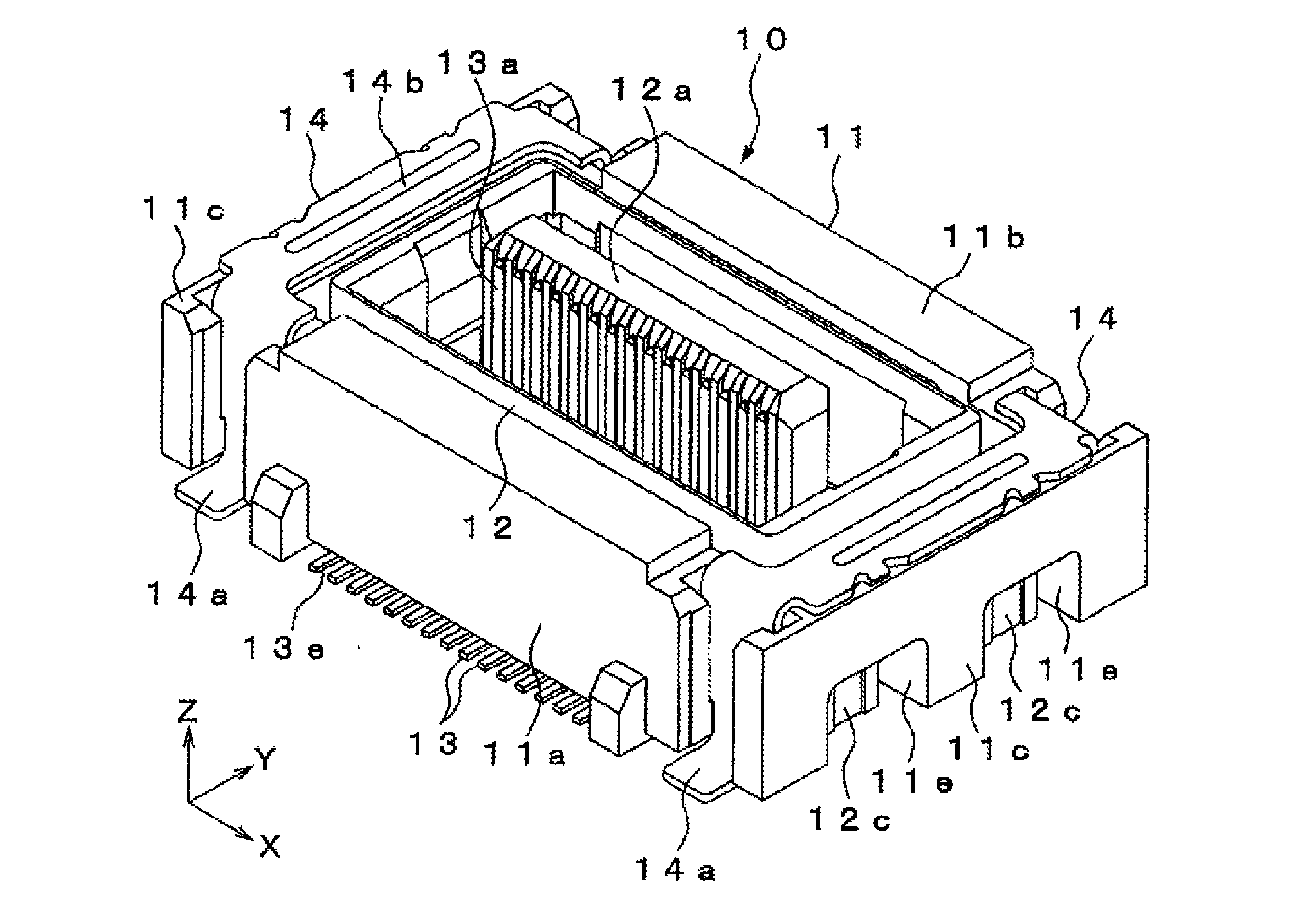
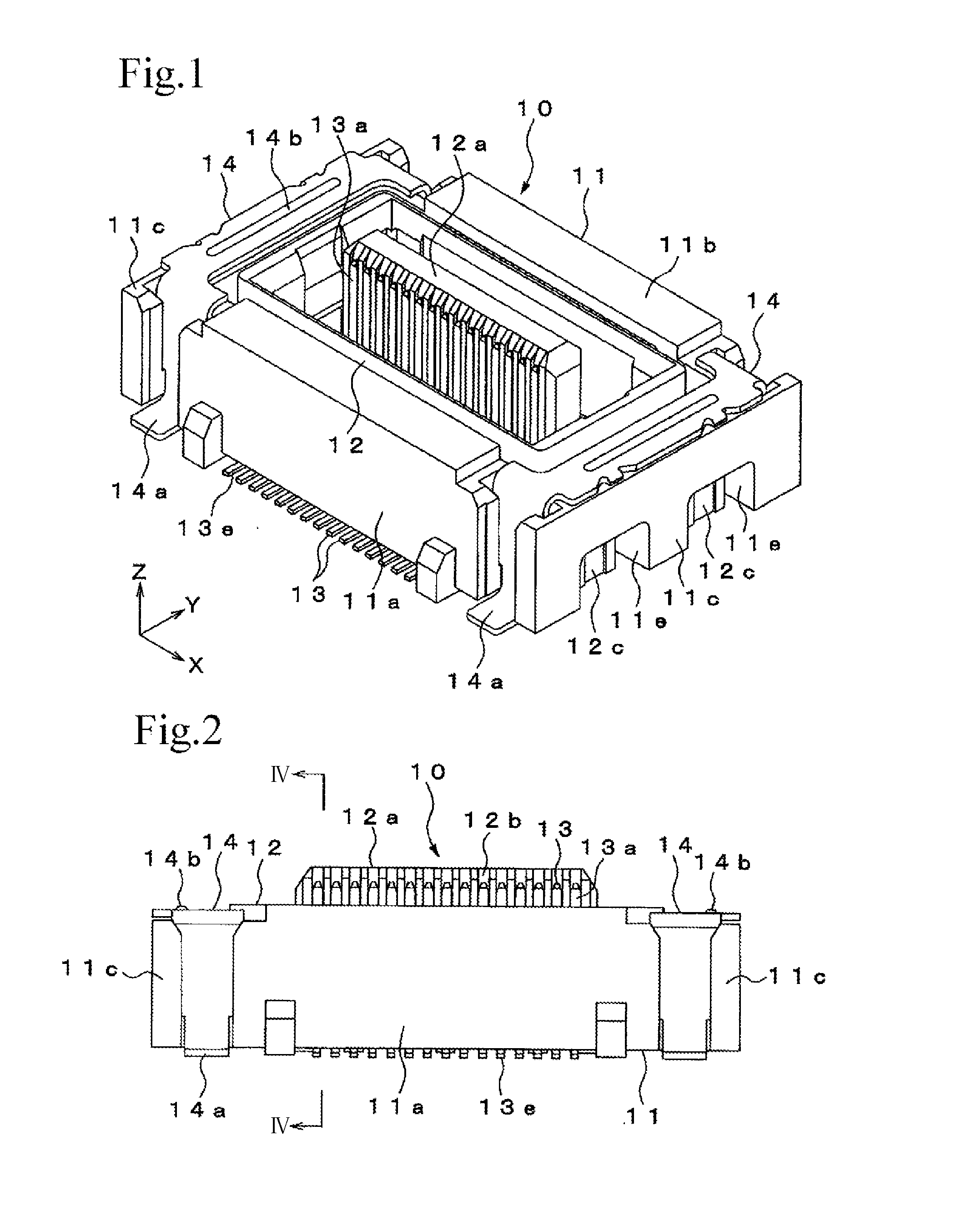
[0031]FIG. 1 through FIG. 16 illustrate a connector unit according to an embodiment of the present invention, used for connecting, for example, a pair of printed substrates to each other. In the drawings, X-direction represents a width direction of the connector, Y-direction represents a front-back direction of the connector, and Z-direction represents an up-down direction of the connector.

[0032]The connector unit according to this embodiment includes a first connector 10 to be attached to a substrate 1 of the pair of substrates 1, 2 disposed such that respective surfaces oppose each other, and a second connector 20 to be attached to the other substrate 2.

[0033]Here, although the second connector 20 is turned upside down in FIG. 15 and FIG. 16 with respect to FIG. 7 to FIG. 12, the up-down direction referred to in the following description will be based on the up-down direction in FIG. 7 to FIG. 12.

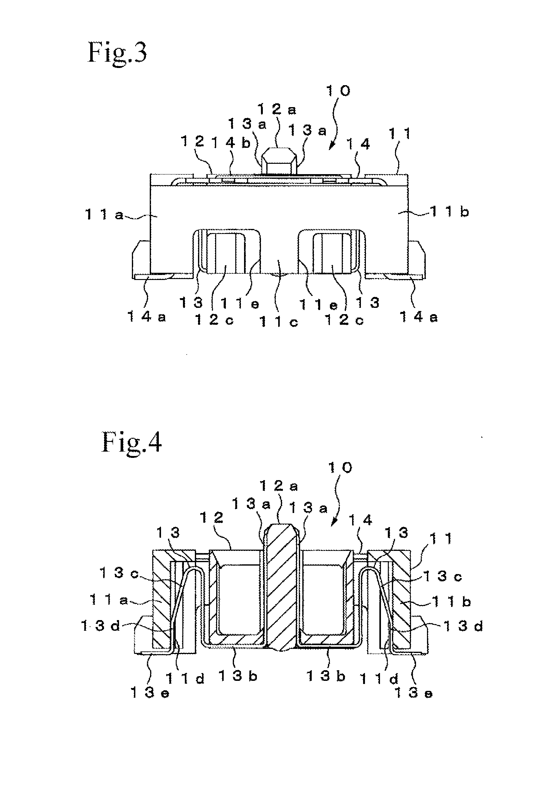
Configuration of First Connector 10

[0034]The first connector 10 includes a first fixe...


PUM


Abstract

The movable portion of the first terminal of the first connector is formed to be larger in the width direction than in the thickness direction, so as to be elastically deformed in the front-back direction of the connector, and the movable portion of the second terminal of the second connector is formed to be larger in the thickness direction than in the width direction, so as to be elastically deformed in the width direction of the connector. Therefore, the movable portions can be formed with an increased cross-sectional area, thereby enabling the allowable current of the terminals to be increased, unlike a configuration in which the movable portion is elastically deformable to a sufficient extent both in the front-back direction and in the width direction of the connector.

Description

BACKGROUND OF THE INVENTION[0001]1. Field of the Invention[0002]The present invention relates to a connector used for connecting, for example, a pair of printed substrates to each other.[0003]2. Description of the Related Art[0004]Connector units are thus far known that include a first connector attached to one of a pair of substrates disposed such that respective surfaces oppose each other, and a second connector attached to the other substrate, the first connector and the second connector being configured to be fitted together to connect the substrates, for example as disclosed in Japanese Unexamined Patent Application Publication No. 2007-18785.[0005]One of the connectors includes a fixed housing to be fixed to the substrate, a movable housing disposed to move relative to the fixed housing in a front-back direction and a width direction of the connector, and a plurality of terminals each having an end portion retained by the movable housing and the other end portion retained by t...

Claims


Application Information

Patent Timeline
IPC IPC(8): H01R35/02H01R13/46
CPCH01R13/46H01R35/02H01R12/716H01R12/91H01R13/6315H01R12/73H01R13/20
Inventor FUNAYAMA, DAISUKEMITSUZUKA, SHIGERUYAMAGUCHI, TOMISABURO
Owner IRISO ELECTRONICS CO LTD
Why Eureka
Try Eureka