Juice extracting device

Inactive Publication Date: 2015-03-12
CHANG TSUNG CHIH
View PDF32 Cites 3 Cited by
  • Summary
  • Abstract
  • Description
  • Claims
  • Application Information

AI Technical Summary

Benefits of technology

The present invention provides a planetary limit switch that solves the issues of conventional juice extracting devices.

Problems solved by technology

In other words, the conventional juice extractor cannot peel the peel of the fruit and spray the juices on the food directly.

Method used


Image

  • Juice extracting device
  • Juice extracting device
  • Juice extracting device

Examples


Embodiment Construction

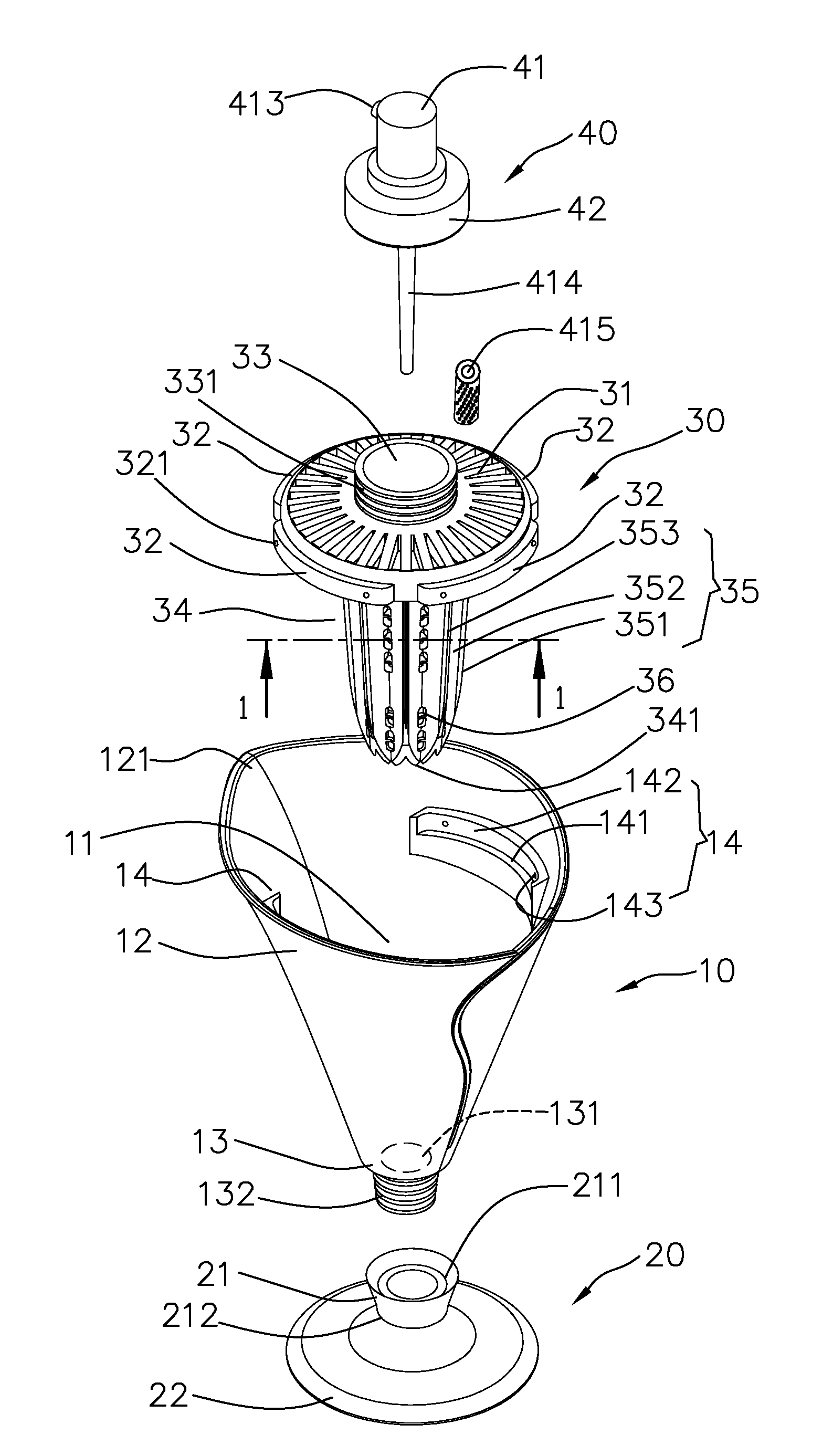
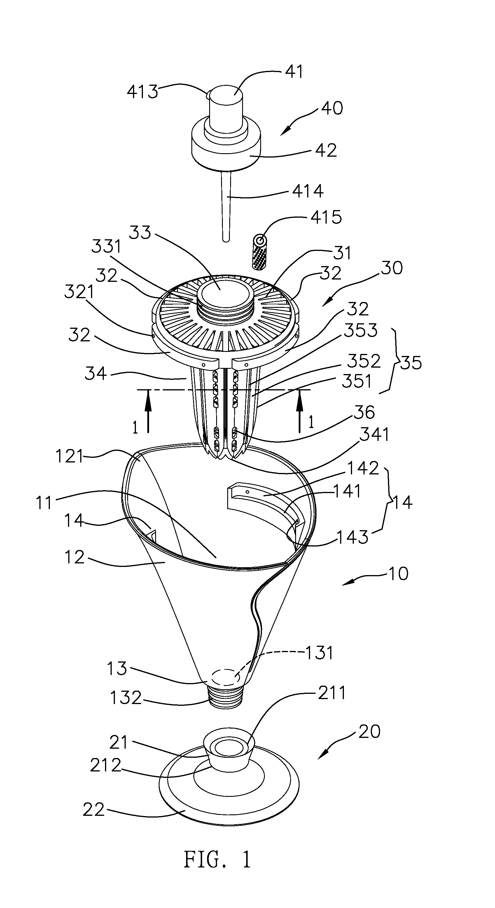
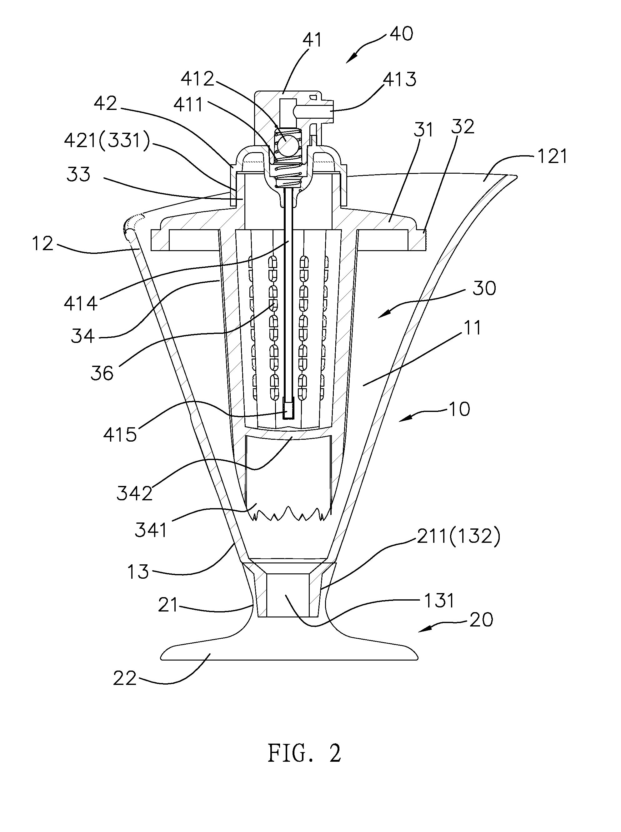
[0023]With reference to FIGS. 1-10, a juice extracting device according to a preferred embodiment of the present invention comprises: a collecting assembly 10, a covering set 20, a body 30, and a pumping member 40.

[0024]The collecting assembly 10 is used to collect juices and includes a cavity 11 defined therein, an open segment 12 formed on a top end of the cavity 11 and having a pouring hole 121 arranged around an inner wall of the open segment 12, a collection segment 13 formed on a bottom end of the cavity 11 and having a guiding hole 131 defined in the collection segment 13 and an outer screwing section 132 arranged around an outer wall of a bottom end thereof, and at least one limiting seat 14 disposed in the cavity 11 adjacent to the open segment 12; wherein each of the at least one limiting seat 14 has a shoulder 141, a stopping face 142 defined over the shoulder 141, and at least one fixing orifice 143 formed on the stopping face 142.

[0025]The covering set 20 is covered on ...


PUM


Abstract

A juice extracting device contains a collecting assembly, a covering set, a body, and a pumping member. The collecting assembly includes a cavity defined, an open segment having a pouring hole, a collection segment having a guiding hole, and at least one limiting seat. The covering set includes a hollow neck and a circular holder. The body includes a filtering disc, a plurality of defining ribs for retaining with the at least one limiting seat, a hollow column; a hollowly conical post having a cutting edge, a stop piece, and an extraction portion. The pumping member is served to draw juices in the collecting assembly and includes a spray head and a drawing tube for drawing the juices.

Description

FIELD OF THE INVENTION[0001]The present invention relates to a juice extracting device which is capable of extracting the juices variously.BACKGROUND OF THE INVENTION[0002]A juice extractor disclosed in U.S. Pat. Nos. 2,212,328 and 2,733,746 is used to extract fruit, such as lemon. However, the fruit has to be peeled by a peel remover in advance, and then pulp of the fruit is crushed to extract juices, thereafter the juices are applied on food. In other words, the conventional juice extractor cannot peel the peel of the fruit and spray the juices on the food directly.[0003]The present invention has arisen to mitigate and / or obviate the afore-described disadvantages.SUMMARY OF THE INVENTION[0004]The primary object of the present invention is to provide a planetary limit switch which is capable of overcoming the shortcomings of the conventional juice extracting device.[0005]To obtain the above objective, a juice extracting device provided by the present invention contains: a collectin...

Claims


Application Information

Patent Timeline
IPC IPC(8): A23N1/02
CPCA23N1/02A47J19/02A23N1/003A23N4/18
Inventor CHANG, TSUNG CHIH ,
Owner CHANG TSUNG CHIH
Why Eureka
Try Eureka