Compact/lightweight gantry and particle beam therapy device using same

a technology of light weight which is applied in the field of compact/lightweight gantry and particle beam therapy device using same, can solve the problems of increasing the demand for enlarging the irradiation available range and further increasing the size of the magnet, and achieve the effect of forming a large irradiation field

Inactive Publication Date: 2015-03-26
HITACHI LTD
View PDF12 Cites 1 Cited by
  • Summary
  • Abstract
  • Description
  • Claims
  • Application Information

AI Technical Summary

Benefits of technology

[0009]According to the present invention, a gantry which can suppress an increase in size of a magnet and can form a large irradiation field can be realized.

Problems solved by technology

Also, demands for enlarging the irradiation available range tend to increase, and this causes a further increase in size of the magnet.

Method used


Image

  • Compact/lightweight gantry and particle beam therapy device using same
  • Compact/lightweight gantry and particle beam therapy device using same
  • Compact/lightweight gantry and particle beam therapy device using same

Examples


first embodiment

[0025]A configuration of a gantry for particle beam therapy according to a first embodiment of the present invention will be described below with reference to FIG. 5.

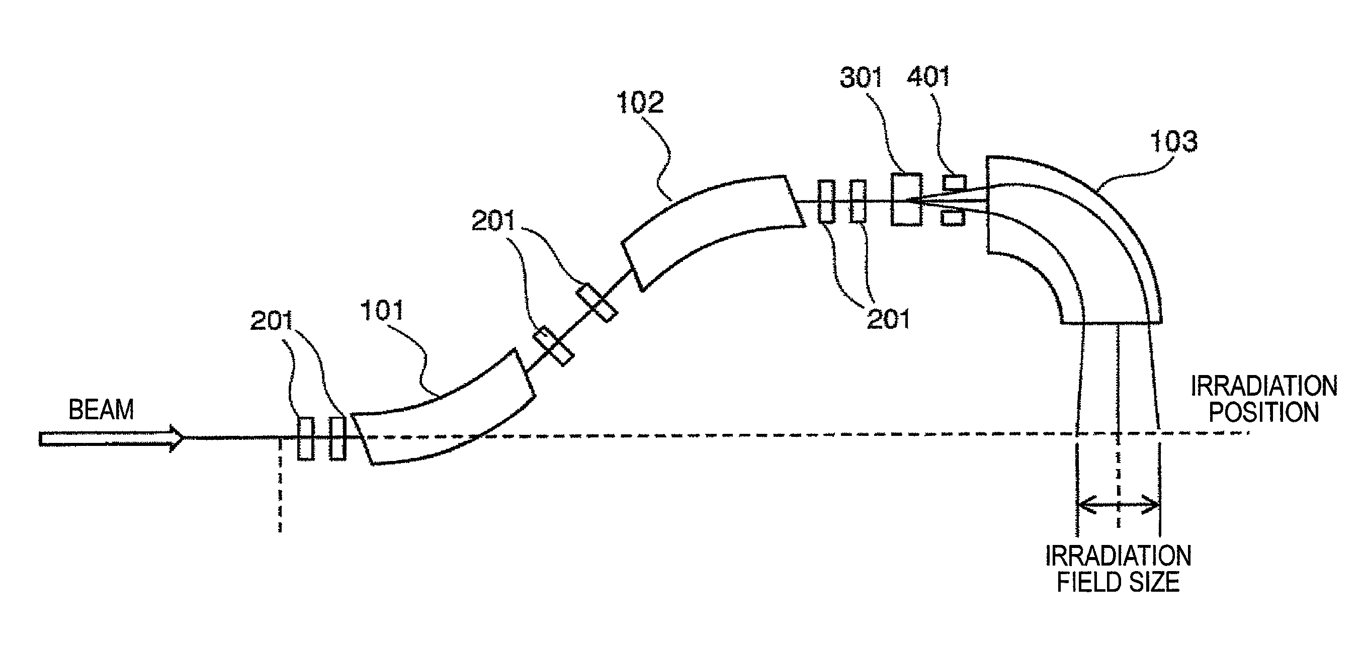
[0026]A particle beam irradiation gantry includes bending magnets 101 to 103 which bend beams, horizontal direction scanning magnets 301 and 302 which scan beam orbits in a horizontal direction, a vertical direction scanning magnet 401 which scans the beam orbit in a vertical direction, a power supply which excites the respective magnets, and a control system (not shown).

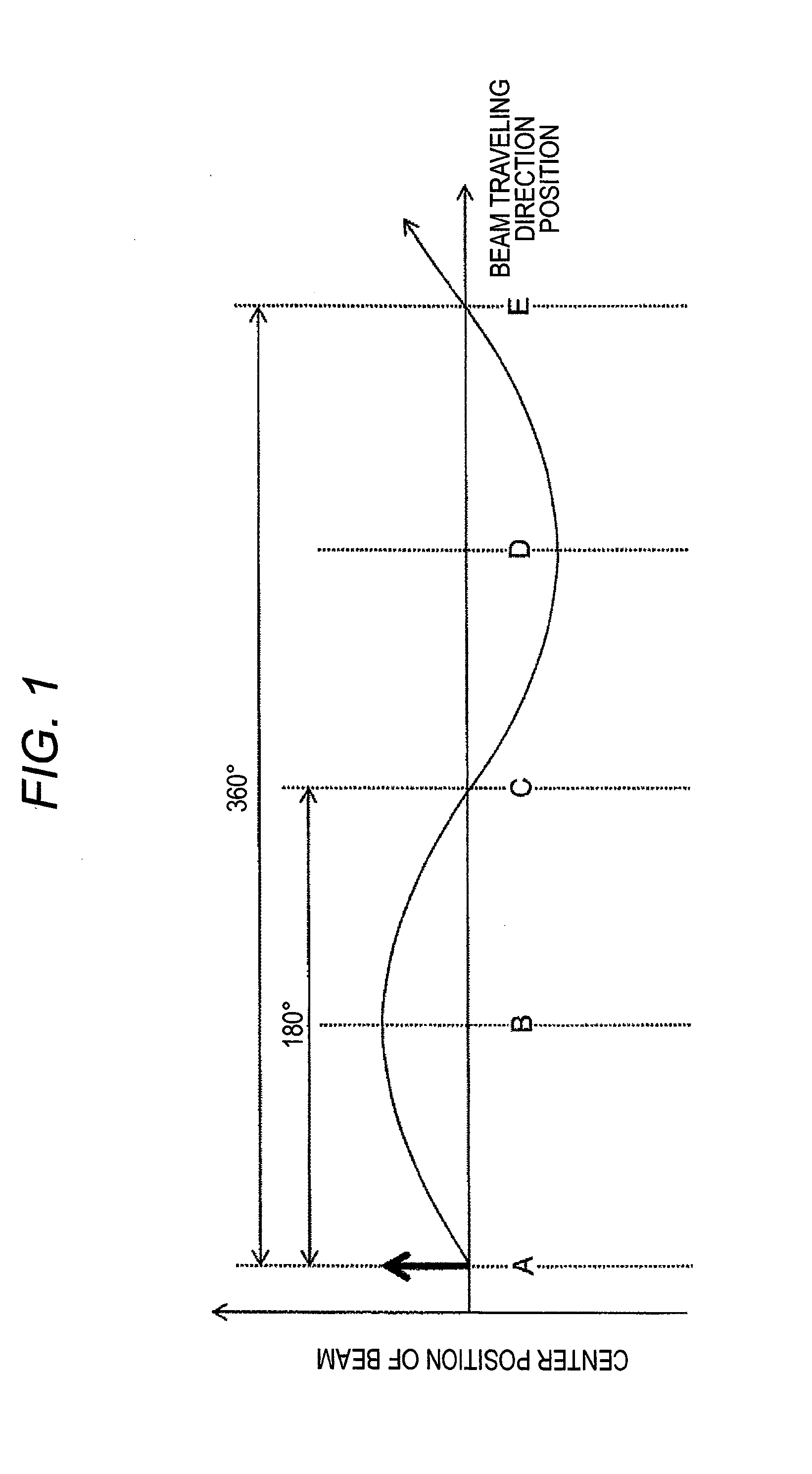
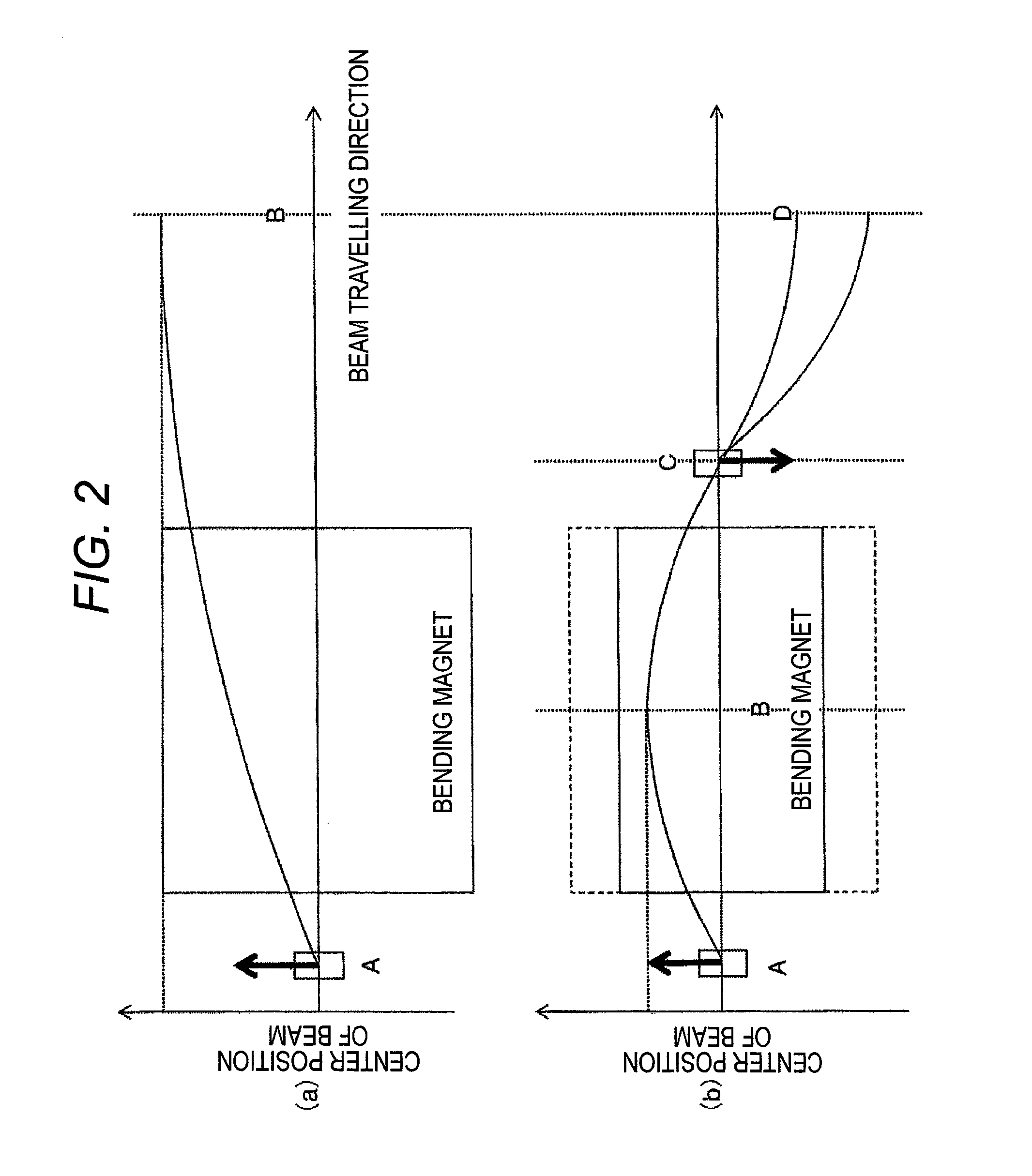
[0027]As mentioned above, the particle beam irradiation gantry includes two horizontal direction scanning magnets. The upstream-side horizontal direction scanning magnet 301 and the downstream-side horizontal direction scanning magnet 302 are arranged at positions where a phase difference therebetween becomes 180°. A bending direction of the downstream-side horizontal direction scanning magnet 302 is an opposite direction relative to a bending direction...

second embodiment

[0034]A configuration of a gantry for particle beam therapy according to a second embodiment of the present invention will be described below with reference to FIG. 6.

[0035]A particle beam irradiation gantry includes bending magnets 101 to 104 which bend beams, horizontal direction scanning magnets 301 and 302 which scan beam orbits in a horizontal direction, a vertical direction scanning magnet 401 which scans the beam orbit in a vertical direction, a power supply which excites the respective magnets, and a control system (not shown).

[0036]As mentioned above, the particle beam irradiation gantry includes two horizontal direction scanning magnets. The upstream-side horizontal direction scanning magnet 301 and the downstream-side horizontal direction scanning magnet 302 are arranged so that a phase difference therebetween becomes 180°.

[0037]The phase difference between the upstream-side horizontal direction scanning magnet 301 and the downstream-side horizontal direction scanning mag...

third embodiment

[0042]A configuration of a gantry for particle beam therapy according to a third embodiment of the present invention will be described below with reference to FIG. 7.

[0043]A particle beam irradiation gantry includes bending magnets 101 to 104 which bend beams, horizontal direction scanning magnets 301 and 302 which scan beam orbits in a horizontal direction, vertical direction scanning magnets 401 and 402, a power supply which excites the respective magnets, and a control system (not shown).

[0044]The particle beam irradiation gantry includes two horizontal direction scanning magnets and two vertical direction scanning magnets. The respective scanning magnets are arranged so that a phase difference between the upstream-side horizontal direction scanning magnet 301 and the downstream-side horizontal direction scanning magnet 302 becomes 180° and a phase difference between the upstream-side vertical direction scanning magnet 401 and the downstream-side vertical direction scanning magne...


PUM


Abstract

To provide a preferred device configuration and arrangement capable of forming a large irradiation field, miniaturizing a gantry and reducing weight of the gantry. A gantry includes a bending magnet configured to bend a beam orbit, a plurality of horizontal direction scanning magnets which are first scanning magnets configured to scan the beam orbit in a horizontal direction which is a first direction, and a vertical direction scanning magnet which is a second scanning magnet configured to scan the beam orbit in a vertical direction which is a second direction. The plurality of horizontal direction scanning magnets is arranged so that θ is equal to or less than 90° when it is assumed that a phase difference between the horizontal direction scanning magnets is 180n°±θ. The bending magnet is arranged between the plurality of horizontal direction scanning magnets.

Description

TECHNICAL FIELD[0001]The present invention relates to a preferred device configuration and arrangement to realize a compact and lightweight gantry for particle beam therapy capable of forming a large irradiation field.BACKGROUND ART[0002]Recently, as one of cancer treatments, a minimally invasive radiation treatment has attracted attention. The treatment applies less load on a human body and can maintain the quality of life at a high level after the treatment. Particularly, a particle beam therapy system using a charged particle beam such as protons or carbon accelerated by an accelerator such as a synchrotron, a cyclotron, or a linear accelerator provides high dose concentration to an affected part and has been expected as a promising system.[0003]In case of irradiating a patient with a beam accelerated by the accelerator, as a unit to realize improvement of the dose concentration to the affected part and reduction of an irradiation dose to vital organs, irradiation using a rotatin...

Claims


Application Information

Patent Timeline
Patent Type & Authority Applications(United States)
IPC IPC(8): A61N5/10
CPCA61N5/1065A61N5/1077A61N5/1043A61N5/1048A61N2005/1087A61N5/1081G21K1/093F04C2270/041
Inventor NODA, FUMIAKIYAMADA, TAKAHIRO
Owner HITACHI LTD
Why Eureka
Try Eureka