Compact and lightweight gantry and particle beam therapy device using the same
a gantry and light technology, applied in the field of compact and lightweight gantry and particle beam therapy devices using the same, can solve the problems of increasing the demand for enlarging the irradiation available range, further increasing the size of the magnet, etc., and achieve the effect of forming a large irradiation field
- Summary
- Abstract
- Description
- Claims
- Application Information
AI Technical Summary
Benefits of technology
Problems solved by technology
Method used
Image
Examples
first embodiment
[0025]A configuration of a gantry for particle beam therapy according to a first embodiment of the present invention will be described below with reference to FIG. 5.
[0026]A particle beam irradiation gantry includes bending magnets 101 to 103 which bend beams, horizontal direction scanning magnets 301 and 302 which scan beam orbits in a horizontal direction, a vertical direction scanning magnet 401 which scans the beam orbit in a vertical direction, a power supply which excites the respective magnets, and a control system (not shown).
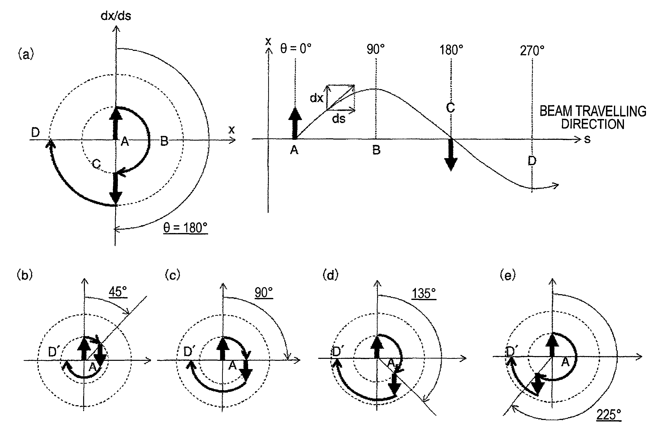
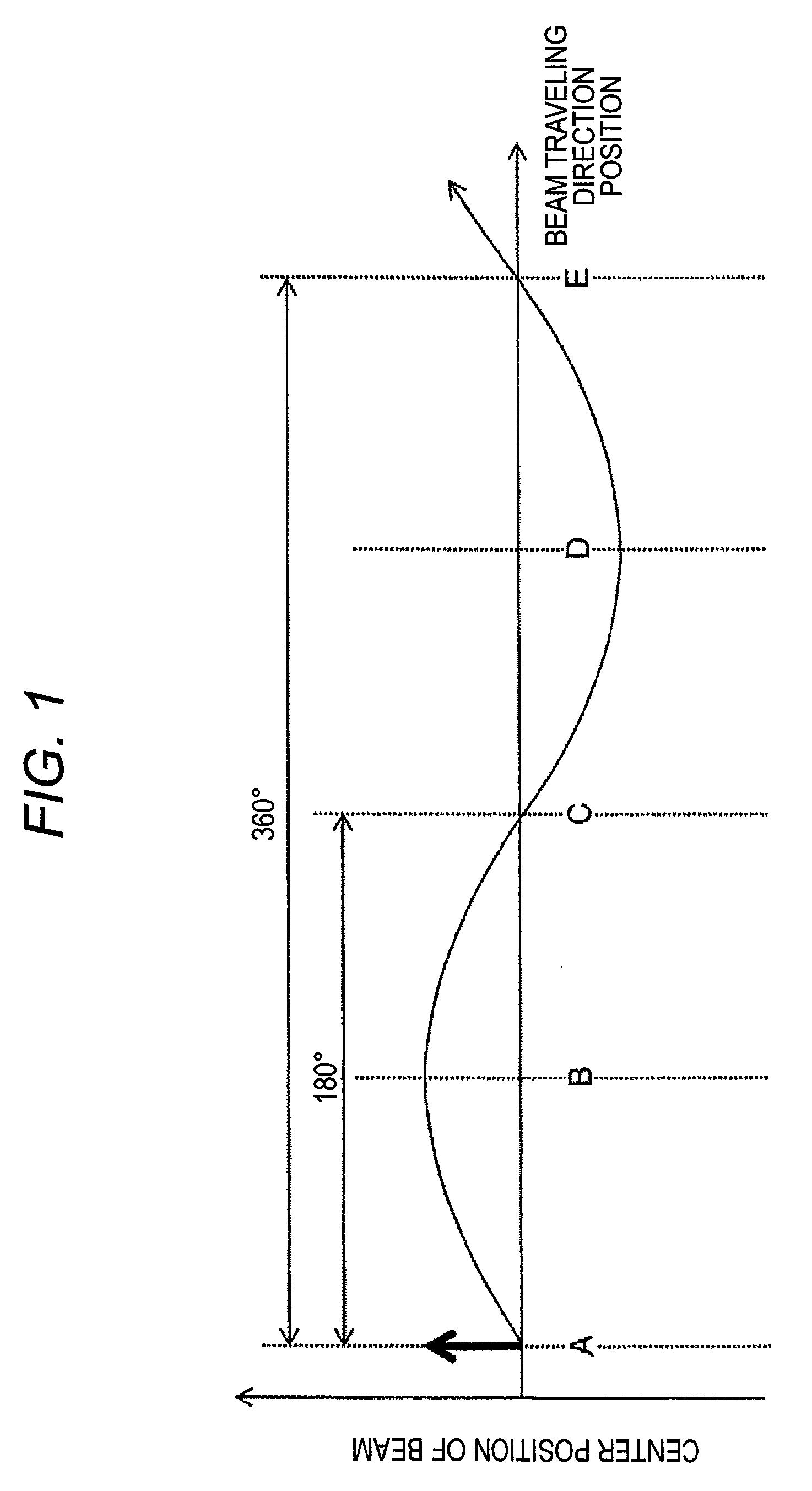
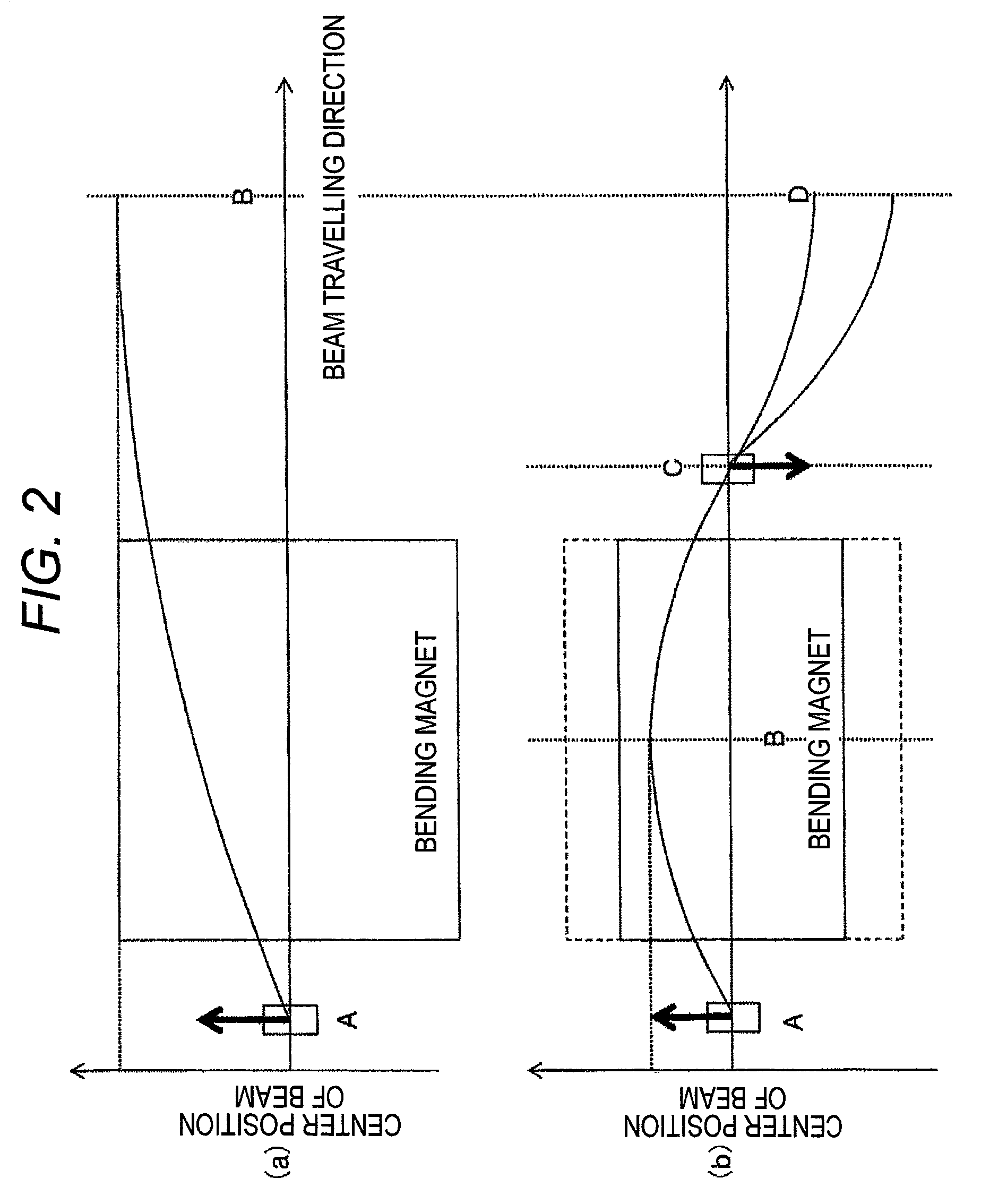
[0027]As mentioned above, the particle beam irradiation gantry includes two horizontal direction scanning magnets. The upstream-side horizontal direction scanning magnet 301 and the downstream-side horizontal direction scanning magnet 302 are arranged at positions where a phase difference therebetween becomes 180°. A bending direction of the downstream-side horizontal direction scanning magnet 302 is an opposite direction relative to a bending direction...
second embodiment
[0034]A configuration of a gantry for particle beam therapy according to a second embodiment of the present invention will be described below with reference to FIG. 6.
[0035]A particle beam irradiation gantry includes bending magnets 101 to 104 which bend beams, horizontal direction scanning magnets 301 and 302 which scan beam orbits in a horizontal direction, a vertical direction scanning magnet 401 which scans the beam orbit in a vertical direction, a power supply which excites the respective magnets, and a control system (not shown).
[0036]As mentioned above, the particle beam irradiation gantry includes two horizontal direction scanning magnets. The upstream-side horizontal direction scanning magnet 301 and the downstream-side horizontal direction scanning magnet 302 are arranged so that a phase difference therebetween becomes 180°.
[0037]The phase difference between the upstream-side horizontal direction scanning magnet 301 and the downstream-side horizontal direction scanning mag...
third embodiment
[0042]A configuration of a gantry for particle beam therapy according to a third embodiment of the present invention will be described below with reference to FIG. 7.
[0043]A particle beam irradiation gantry includes bending magnets 101 to 104 which bend beams, horizontal direction scanning magnets 301 and 302 which scan beam orbits in a horizontal direction, vertical direction scanning magnets 401 and 402, a power supply which excites the respective magnets, and a control system (not shown).
[0044]The particle beam irradiation gantry includes two horizontal direction scanning magnets and two vertical direction scanning magnets. The respective scanning magnets are arranged so that a phase difference between the upstream-side horizontal direction scanning magnet 301 and the downstream-side horizontal direction scanning magnet 302 becomes 180° and a phase difference between the upstream-side vertical direction scanning magnet 401 and the downstream-side vertical direction scanning magne...
PUM
 Abstract
Description
Claims
Application Information
 - R&D
- Intellectual Property
- Life Sciences
- Materials
- Tech Scout
- Unparalleled Data Quality
- Higher Quality Content
- 60% Fewer Hallucinations
Browse by: Latest US Patents, China's latest patents, Technical Efficacy Thesaurus, Application Domain, Technology Topic, Popular Technical Reports.
© 2025 PatSnap. All rights reserved.Legal|Privacy policy|Modern Slavery Act Transparency Statement|Sitemap|About US| Contact US: help@patsnap.com


