
Damper, head unit, liquid jetting apparatus, and air-discharge method of damper

Active Publication Date: 2010-08-26
BROTHER KOGYO KK
View PDF8 Cites 10 Cited by
  • Summary
  • Abstract
  • Description
  • Claims
  • Application Information

AI Technical Summary

Benefits of technology

[0009]Therefore, an object of the present invention is to provide a damper which is capable of facilitating an improvement in an air-discharge efficiency while suppressing an increase in the size of the damper, and moreover, an object of the present invention is to provide a damper which is capable of facilitating an improvement in a pressure relaxation efficiency while suppressing the increase in the size of the damper. Furthermore, an object of the present invention is to provide a head unit which includes such damper, a liquid jetting apparatus, and an air-discharge method of the damper.
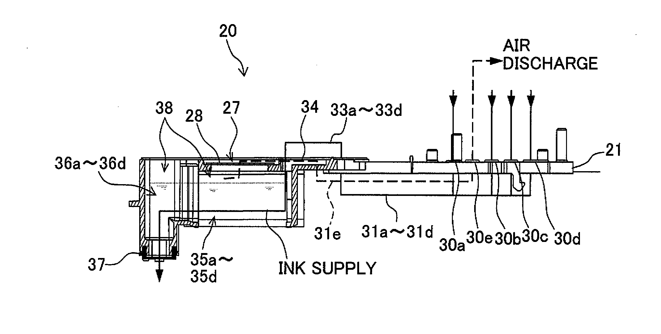
[0011]a reservoir which stores the liquid and damps a pressure fluctuation in the liquid, the reservoir including a gas-liquid separation membrane which defines an upper portion of the reservoir, and a damper film which has a flexibility and which defines the reservoir at a lower side of the gas-liquid separation membrane.
[0022]In any of the cases, since the damper is provided with both, the damper function and the air-discharge function, it is not necessary to provide an air-discharge mechanism separately, and it is possible to facilitate small sizing of the head unit and the liquid jetting apparatus.
[0028]Moreover, according to a fifth aspect of the present invention, there is provided an air discharge method of damper including, a pressurizing step of applying a positive pressure to the reservoir of the damper as defined in claim 1 to discharge an air in the reservoir via the gas-liquid separation membrane which covers the upper portion of the reservoir. By making such an arrangement, it is possible to carry out the air discharge through the gas-liquid separation membrane efficiently by letting the reservoir to be at a positive pressure by using a pump for supplying an ink from the ink cartridge to the damper, and it is not necessary to provide an exclusive pump etc. for letting the reservoir to be at positive pressure.

Problems solved by technology

In the printer as described above, when the upper-opening of the ink outflow channel in which the gas-liquid separation membrane is provided for improving the air-discharge efficiency is made larger, the small sizing of the damper becomes difficult.
When an attempt is made to facilitate the improvement in the pressure relaxation efficiency in the above described printer, dimensions in a plan view of the ink reservoir have to be made substantial for making an area of the flexible film substantial, then the small sizing of the damper becomes difficult.

Method used


Image

  • Damper, head unit, liquid jetting apparatus, and air-discharge method of damper
  • Damper, head unit, liquid jetting apparatus, and air-discharge method of damper
  • Damper, head unit, liquid jetting apparatus, and air-discharge method of damper

Examples


Embodiment Construction

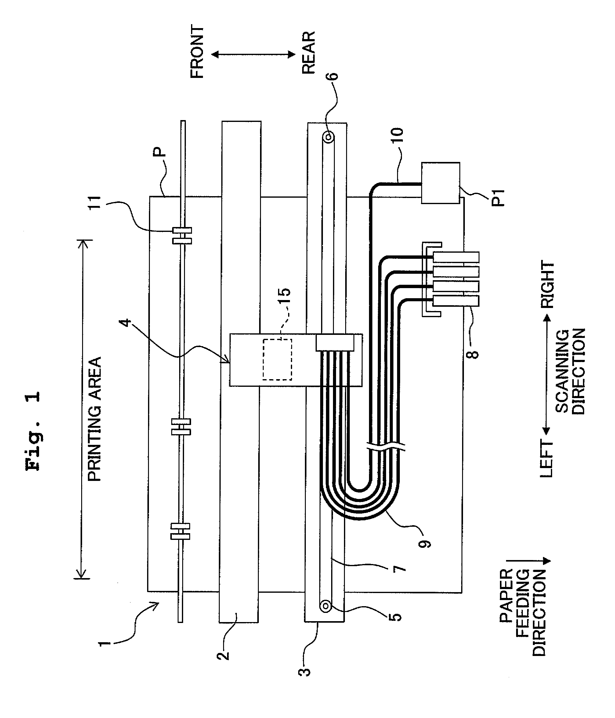
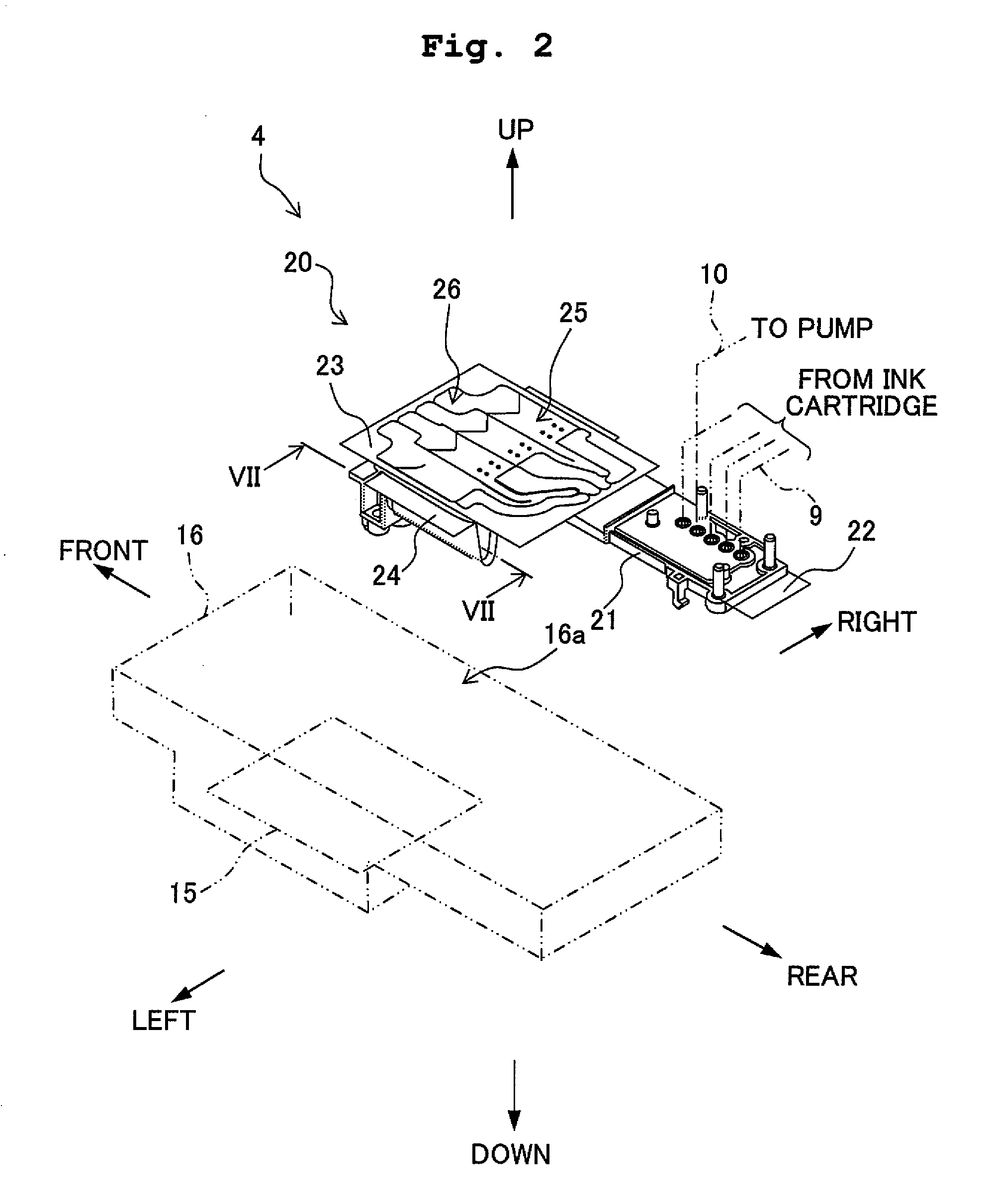
[0041]A damper and an air-discharge method thereof according to an embodiment of present teaching will be described below with reference to the accompanying diagram. In the following, an example in which the damper is applied to an ink-jet printer (hereinafter, called as a ‘printer’) having a jetting head is explained. However, the present teaching is not restricted to an application to the printer, and is also applicable to all kinds of liquid jetting apparatuses which jet a liquid other than ink. Moreover, in the following description, each of directions namely ‘up’, ‘down’, ‘left’, ‘right’, ‘front’, and ‘rear’ is defined based on directions shown in FIG. 2. In other words, a direction of jetting ink from the jetting head is defined as the downward direction, and an opposite direction thereof is defined as the upward direction. A scanning direction of the jetting head is defined as the left-right direction, and directions orthogonal to both the vertical direction (up-down directio...


PUM


Abstract

A damper includes a reservoir which stores a liquid and damps a pressure fluctuation in the liquid and includes a gas-liquid separation membrane which demarcates an upper portion of the reservoir, and a flexible damper film which demarcates the reservoir at a lower side of the gas-liquid separation membrane. Accordingly, there is provided a damper which is capable of improving an air-discharge efficiency while suppressing an increase in the size, and moreover improving a pressure relaxation efficiency.

Description

CROSS REFERENCE TO RELATED APPLICATION[0001]The present application claims priority from. Japanese Paten Application No. 2009-042112, filed on Feb. 25, 2009, the disclosure of which is incorporated herein by reference in its entirety.BACKGROUND OF THE INVENTION[0002]1. Field of the Invention[0003]The present invention relates to a damper, accommodated in a liquid jetting apparatus such as an ink-jet printer, which has a reservoir storing a liquid for relaxing pressure fluctuation of a liquid; a head unit which includes the damper; a liquid jetting apparatus; and a method of discharging air from the reservoir of the damper.[0004]2. Description of the Related Art[0005]An ink jet-printer, as an example of a liquid jetting apparatus, mainly includes a liquid supply unit having: a jetting head in which nozzles are formed; a damper which is connected to the jetting head, which stores a small amount of ink and which absorbs a pressure fluctuation of ink; and a casing which accommodates the...

Claims


Application Information

Patent Timeline
IPC IPC(8): B41J2/17
CPCB41J2/175
Inventor TAKATA, MASAYUKI
Owner BROTHER KOGYO KK
Learn More