Fuel cell system and control method thereof

Active Publication Date: 2019-09-26
HONDA MOTOR CO LTD
View PDF0 Cites 2 Cited by
  • Summary
  • Abstract
  • Description
  • Claims
  • Application Information

AI Technical Summary

Benefits of technology

[0010]According to the configuration above, the fuel gas injected from the plurality of injectors is guided to the diffuser through the nozzle of the ejector, so that the circulation characteristics of the fuel off-gas can be kept equal irrespective of from which of the injectors the fuel gas is injected. This makes it possible to stably circulate the fuel off-gas to the fuel cell by a simple control.
[0011]Further, when the fuel cell is in the first load state, the first injection control mode is performed in which the plurality of injectors intermittently inject the fuel gas in an alternate manner, once at a time or multiple times at a time. Thus, even in the first load state in which the amount of necessary fuel gas is relatively small, the injection time during which the injectors inject the fuel gas each time can be equal to or longer than a drainage necessary time. This allows the produced water in the fuel cell to be discharged efficiently.
[0012]Fur

Problems solved by technology

It is therefore not easy to stably circulate the fuel off-gas to the fuel cell.
However, in Japanese Laid-Open Patent Publication No. 2011-179333, since the fuel gas is alternately injected from two injectors, it is n

Method used


Image

  • Fuel cell system and control method thereof
  • Fuel cell system and control method thereof
  • Fuel cell system and control method thereof

Examples


Example

[0040]The fuel cell system and control method thereof according to the present invention will now be described in detail in conjunction with preferred embodiments with reference to the accompanying drawings.

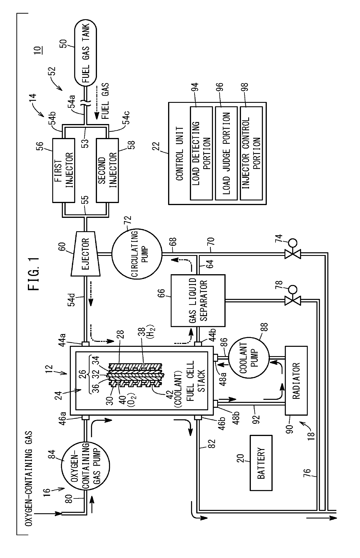
[0041]As shown in FIG. 1, a fuel cell system 10 according to an embodiment of the present invention is mounted on a fuel cell vehicle (not shown) such as a fuel-cell electric car or the like, for example.

[0042]The fuel cell system 10 includes a fuel cell stack 12 (fuel cell). The fuel cell stack 12 is provided with a fuel gas supply device 14 for supplying a fuel gas, e.g. hydrogen gas, an oxygen-containing gas supply device 16 for supplying an oxygen-containing gas, e.g. the air, and a coolant supply device 18 for supplying a coolant. The fuel cell system 10 further includes a battery 20 as an energy storage device, and a control unit 22 as a system control device.

[0043]In the fuel cell stack 12, a plurality of power generation cells 24 are stacked in a horizontal direction or v...


PUM


Abstract

A fuel cell system includes a nozzle for guiding a fuel gas injected from a first injector and a second injector to a diffuser. An injector control portion performs a first injection control mode when a fuel cell stack is in a first load state. When the fuel cell stack is in a second load state, the injector control portion switches between a second injection control mode and a third injection control mode depending on the circumstances.

Description

CROSS-REFERENCE TO RELATED APPLICATION[0001]This application is based upon and claims the benefit of priority from Japanese Patent Application No. 2018-054263 filed on Mar. 22, 2018, the contents of which are incorporated herein by reference.BACKGROUND OF THE INVENTIONField of the Invention[0002]The present invention relates to a fuel cell system including a plurality of injectors provided in parallel on a fuel gas supply path for guiding a fuel gas to a fuel cell, and to a control method thereof.Description of the Related Art[0003]Japanese Laid-Open Patent Publication No. 2011-179333 discloses a technical idea for circulating a fuel off-gas discharged from a fuel cell, where two injectors disposed on a fuel gas supply path alternately inject a fuel gas from different directions to a throat portion of a diffuser that constitutes an ejector.SUMMARY OF THE INVENTION[0004]According to Japanese Laid-Open Patent Publication No. 2011-179333 above, the two injectors alternately inject the ...

Claims


Application Information

Patent Timeline
IPC IPC(8): H01M8/04082H01M8/04089H01M8/04746
CPCH01M8/04753H01M8/04097H01M8/04201H01M8/0662H01M8/04388Y02P70/50Y02E60/50
Inventor MIZUMOTO, KAZUYAKATO, KOICHISAITO, YOICHIRO
Owner HONDA MOTOR CO LTD
Why Eureka
Try Eureka