
Liquid ejecting apparatus, control method of liquid ejecting head, and control method of liquid ejecting apparatus

Inactive Publication Date: 2015-12-17
SEIKO EPSON CORP
View PDF4 Cites 0 Cited by
  • Summary
  • Abstract
  • Description
  • Claims
  • Application Information

AI Technical Summary

Benefits of technology

The invention provides a liquid ejecting apparatus that can efficiently remove bubbles from nozzles while reducing the consumption of liquid. The method involves maintaining a bubble in the nozzle and then quickly discharging it with ink before it can escape and mix into the pressure chamber. This reduces the amount of liquid consumed and the likelihood of bubbles becoming trapped in the system. The method also involves controlling the meniscus in the nozzle to prevent bubbles from escaping and mixing into the pressure chamber, resulting in more efficient bubble removal and reduced liquid consumption.

Problems solved by technology

However, when the bubble is mixed in the liquid in the nozzle by wiping the nozzle surface, in the flushing process of the related art, since an ability of discharging the bubble in liquid in the nozzle is not sufficient, there is a problem in that the liquid is uneconomically consumed in the process.
Particularly, when the bubble in the liquid in the nozzle is moved to the pressure chamber side, the bubble is more difficult to be discharged in the flushing process.
In this case, the maintenance process (so called cleaning process) in which the liquid is sucked from the nozzle by negatively pressurizing the nozzle surface is required to be performed; however, in this process, there is a problem in that the liquid is consumed much more than the liquid used in the flushing process.

Method used


Image

  • Liquid ejecting apparatus, control method of liquid ejecting head, and control method of liquid ejecting apparatus
  • Liquid ejecting apparatus, control method of liquid ejecting head, and control method of liquid ejecting apparatus
  • Liquid ejecting apparatus, control method of liquid ejecting head, and control method of liquid ejecting apparatus

Examples


Embodiment Construction

[0028]Hereinafter, embodiments of the invention will be described with reference to attached drawings. In the embodiments as follows, each of the embodiments are limited as appropriate examples of the invention; however, a range of the invention is not limited to a description as long as the description which is limited to the invention is not disclosed in the description hereinafter. In addition, hereinafter, as a liquid ejecting apparatus of the invention, an ink jet recording apparatus (hereinafter, referred to as a printer) is described as an example.

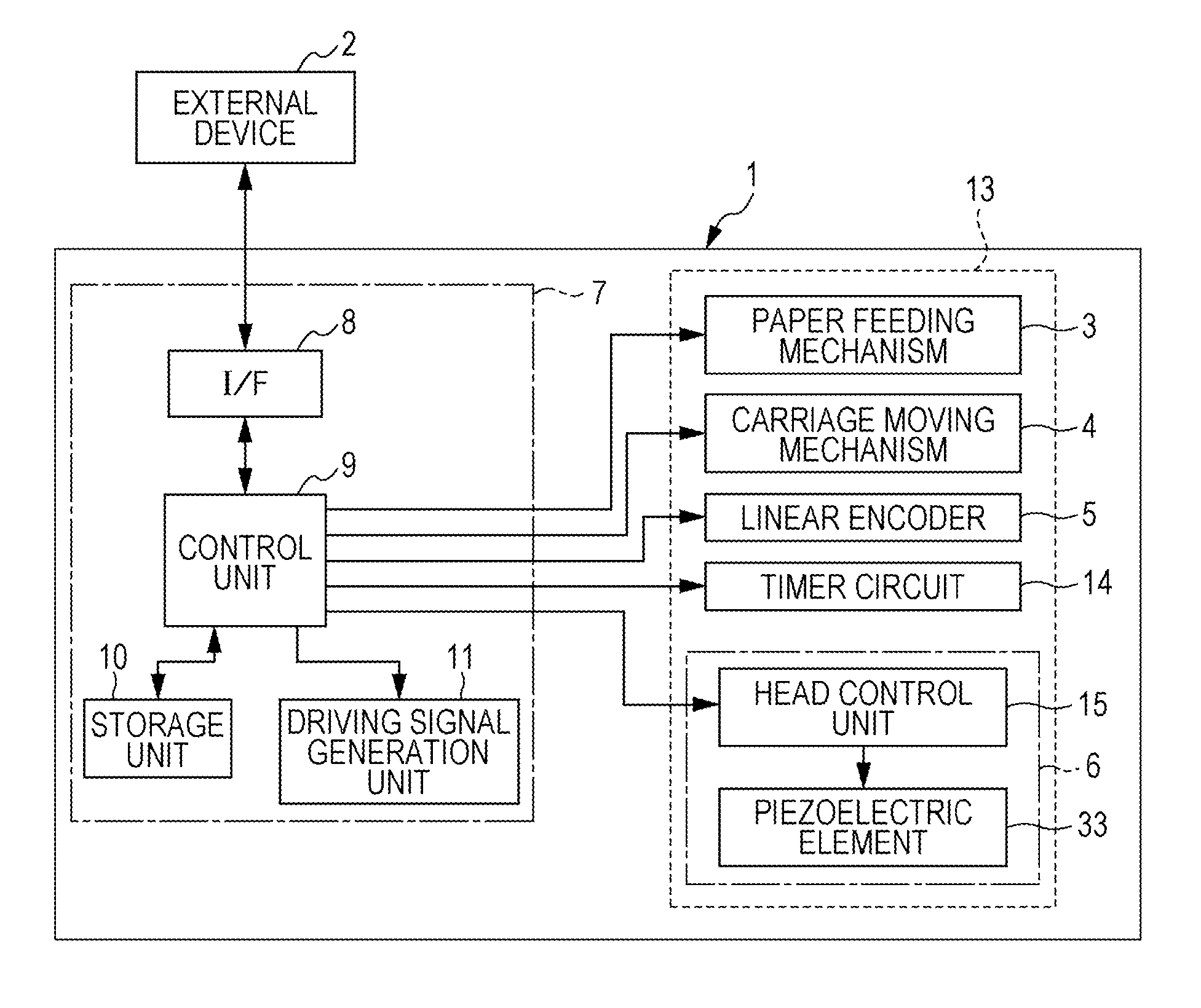
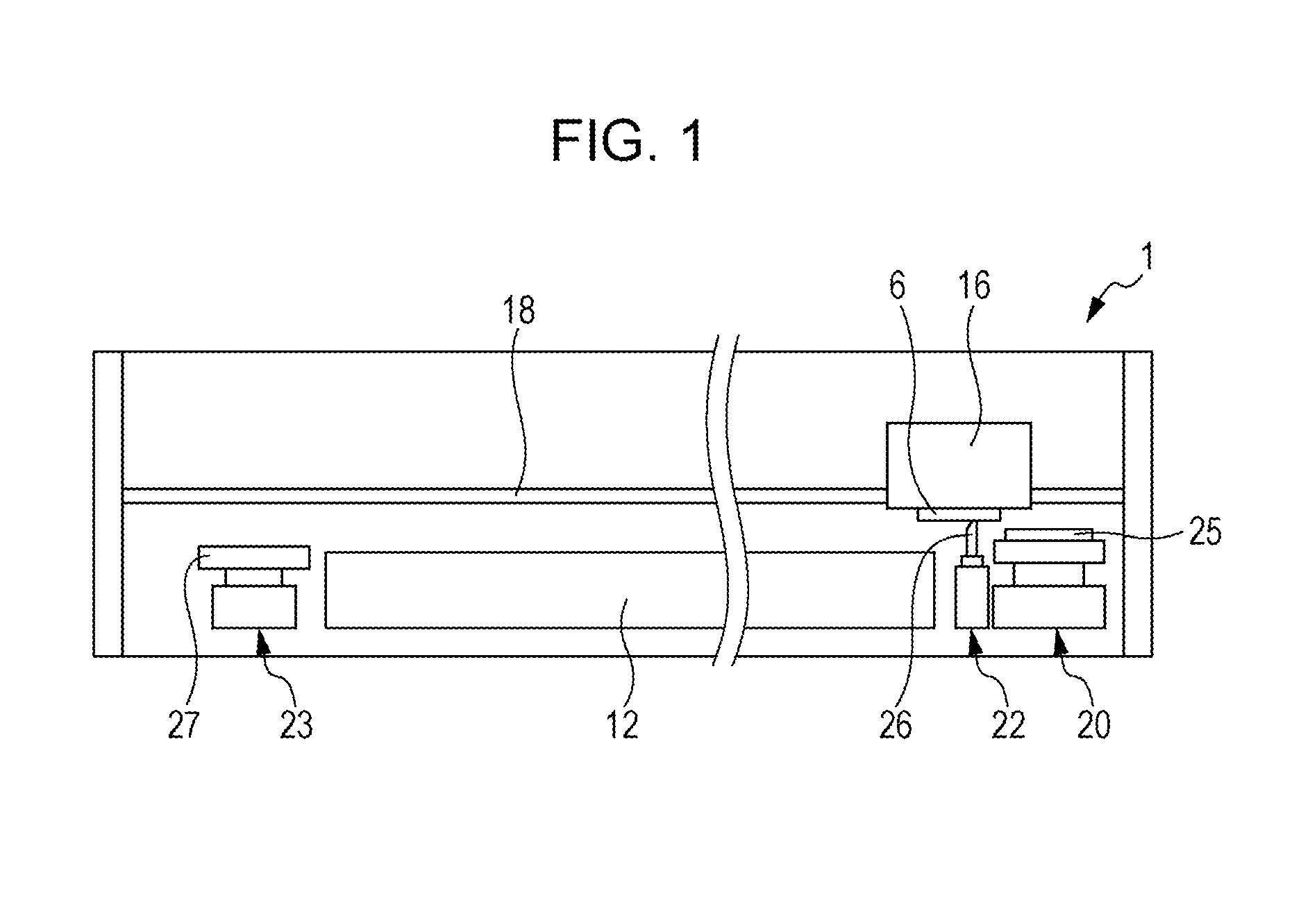
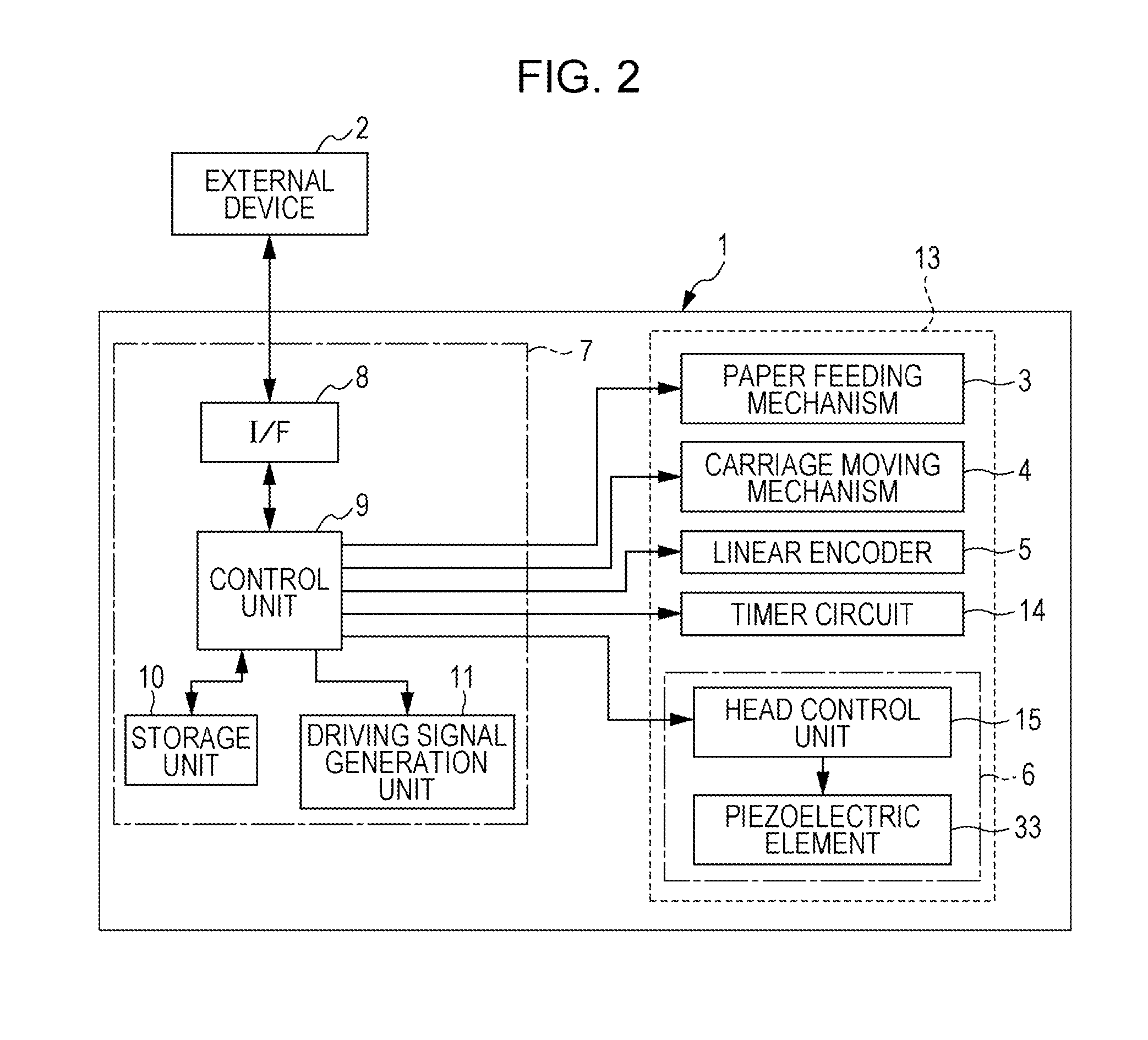
[0029]FIG. 1 is a front view describing an internal configuration of a printer 1, and FIG. 2 is a block diagram describing an electrical configuration of the printer 1. The printer 1 in the embodiment is electrically connected to, for example, an external device 2 of an electronic device such as a computer in a wired or wireless state and receives printing data according to an image, or the like, for printing the image or a text to ...


PUM


Abstract

When a length of a central axis direction of a straight part is L [μm], and a floating speed of a bubble set according to a diameter d of a nozzle, a density ρ of ink, and the diameter r of the bubble is Vr [μm / s], a flushing process is performed by driving an actuator with a flushing pulse within (L+5) / Vr [s] after a nozzle surface is wiped with a wiper so as to perform an ejecting operation. The flushing pulse in the flushing process is preferably a driving waveform which does not actively draw a meniscus in the nozzle toward a pressure chamber side from the initial position, and makes the ink be ejected from the nozzle by extruding the meniscus toward an ejecting side.

Description

CROSS REFERENCE TO RELATED APPLICATIONS[0001]This application claims priority to Japanese Patent Application No. 2014-120711 filed on Jun. 11, 2014. The entire disclosure of Japanese Patent Application No. 2014-120711 is hereby incorporated herein by reference.BACKGROUND[0002]1. Technical Field[0003]The present invention relates to a liquid ejecting apparatus such as an ink jet recording apparatus, a control method of a liquid ejecting head mounted on the liquid ejecting apparatus, and a control method of the liquid ejecting apparatus, and more particularly, to a liquid ejecting apparatus which performs a maintenance process to recover an ejecting ability of a liquid ejecting head, a control method of the liquid ejecting head, and a control method of the liquid ejecting apparatus.[0004]2. Related Art[0005]A liquid ejecting apparatus is a device which includes a liquid ejecting head and ejects (discharges) various liquids using the liquid ejecting head. As such a liquid ejecting appa...

Claims


Application Information

Patent Timeline
IPC IPC(8): B41J2/165
CPCB41J2/16535B41J2/16526B41J2/16538B41J2002/16573
Inventor ZHANG, JUNHUAKANAYA, MIHARU
Owner SEIKO EPSON CORP
Learn More