Image forming apparatus

Inactive Publication Date: 2011-06-23
CANON KK
View PDF6 Cites 3 Cited by
  • Summary
  • Abstract
  • Description
  • Claims
  • Application Information

AI Technical Summary

Benefits of technology

[0004]A principal object of the present invention is to provide an image forming apparatus capable of discharging toner e

Problems solved by technology

However, when the amount of the toner deposited on the charging member is large, there arises a problem tha

Method used


Image

  • Image forming apparatus
  • Image forming apparatus
  • Image forming apparatus

Examples


Example

Embodiment 1

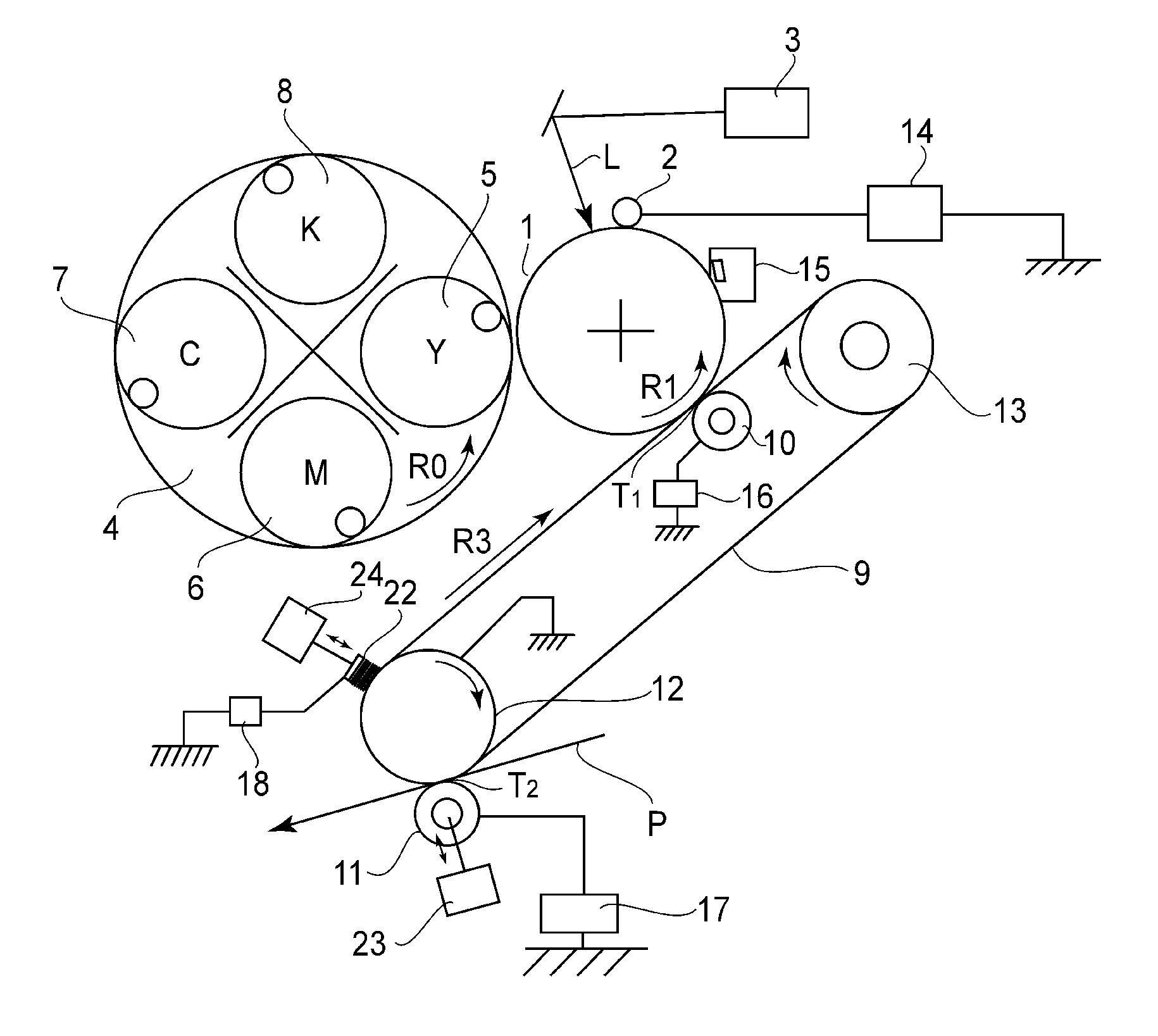
[0022]FIG. 1 is a schematic sectional view showing an image forming apparatus in this embodiment. In this embodiment, the image forming apparatus is of an electrophotographic type and of an intermediary transfer type, in which toner images of a plurality of colors (e.g., four colors) are successively transferred onto a rotating intermediary transfer member a plurality of times (e.g., four times) and then are collectively transferred from the intermediary transfer member onto a transfer material at a secondary transfer portion. Hereinafter, this type is referred to as a four-path type.

[0023]In this embodiment, the image forming apparatus includes a drum-like electrophotographic photosensitive member 1 as an image bearing member (hereinafter referred to as a photosensitive drum 1). Around the photosensitive drum 1, a charging device 2, a rotary 4 including developing devices 5, 6, 7 and 8, an intermediary transfer belt (intermediary transfer member) 9 and a primary transfe...

Example

[0042]As Comparative Embodiment, in the state in which the electroconductive brush 22 was contacted to the intermediary transfer belt 9, the voltages were applied to the electroconductive brush 22 and then the amount of the toner discharged from the electroconductive brush 22 was measured (FIG. 4).

[0043]Specifically, each of the voltages of −100 V, −400 V, −700 V and −1000 V was applied to the electroconductive brush 22 and then the discharge toner amount at each of the voltages was measured.

[0044]FIG. 5 is a result of study on the discharge toner amount with respect to the voltage applied to the electroconductive brush 22 in Embodiment 1 and Comparative Embodiment. As is apparent from FIG. 5, even at any voltage, it is understood that the discharge toner amount in Embodiment 1 is larger than that in Comparative Embodiment.

[0045]In the state in which the electroconductive brush 22 is contacted to the intermediary transfer belt 9, almost of the current generated by the voltage applic...

Example

Embodiment 2

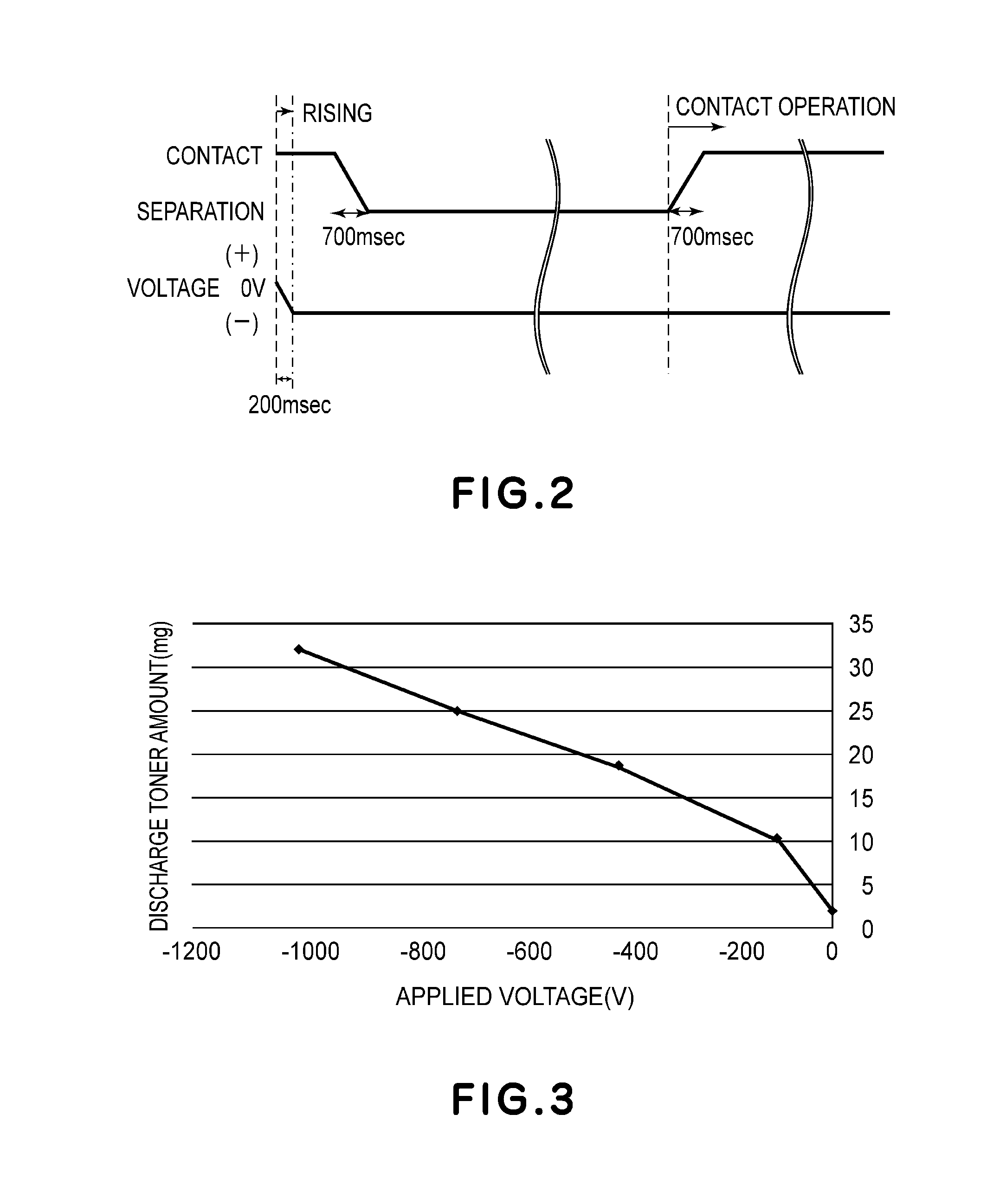
[0048]In the case where the image formation is continuously effected (hereinafter referred to as continuous print), the electroconductive brush 22 is contacted to the intermediary transfer belt 9 immediately before the secondary transfer is started. Then, after the contact and before the secondary transfer residual toner passes through the electroconductive brush 22, the DC voltage of the photosensitive drum is applied to the electroconductive brush 22. The residual toner passes through the electroconductive brush 22 is positively charged, thus being transferred onto the photosensitive drum 1. Further, the primary transfer of a subsequent toner image is performed immediately after the primary transfer of the preceding toner image of black, thus being timed to the transfer of the residual toner. A trailing end of the residual toner passes through the electroconductive brush 22 and thereafter the voltage applied to the electroconductive brush 22 is cut off and the electroc...


PUM


Abstract

An image forming apparatus includes a drum for bearing a toner image; a rotatable belt onto which the toner image is to be transferred from the drum; a primary transfer member for primary transferring the toner image from the drum onto the belt; a secondary transfer member for secondary transferring the toner image from the belt onto a transfer material; and a charging member for electrically charging toner remaining on the belt. The image forming apparatus is capable of executing a belt cleaning mode in which the toner remaining on the belt is electrically charged, and a charging member cleaning mode in which the toner is transferred from the charging member onto the belt and then onto the drum. When the charging member cleaning mode is executed, the charging member is moved at least once from a belt separation position or away from a belt contact position.

Description

FIELD OF THE INVENTION AND RELATED ART[0001]The present invention relates to an image forming apparatus such as an electrophotographic printer or an electrophotographic copying machine.[0002]As the image forming apparatus such as the electrophotographic printer or copying machine, an image forming apparatus of an intermediary transfer type in which a toner image is formed on an image bearing member and is primary-transferred from the image bearing member onto an intermediary transfer member and then is secondary-transferred from the intermediary transfer member onto a transfer material has been known. In such an image forming apparatus, there is a need to collect transfer residual toner, which has not been secondary-transferred from the intermediary transfer member on the transfer material, from the intermediary transfer member. Japanese Laid-Open Patent Application (JP-A) Hei 10-49023 discloses a constitution, as a residual toner collecting constitution, in which the residual toner...

Claims


Application Information

Patent Timeline
IPC IPC(8): G03G15/16G03G21/00
CPCG03G15/161
Inventor ISHIZUMI, KEISUKEAKIZUKI, TOMOOSHINJI, TAKESHISAITO, SEIJI
Owner CANON KK
Why Eureka
Try Eureka