This helps you quickly interpret patents by identifying the three key elements:
Problems solved by technology
Method used
Benefits of technology
Benefits of technology
[0006] The present invention is achieved in view of the above issues, and its object is to provide an AC generator for a vehicle that has a high cooling ability for the rectifier device without raising an ability of a cooling fan and that can efficiently discharge muddy water intruded inside of a protection cover.
Problems solved by technology
Currently, a large power output is demanded for AC generator for vehicle, making a key issue in improving a cooling ability for a rectifier located therein, which generates a large amount of heat by a large current flowing therethrough.
It is considered to raise an ability of fans for cooling the rectifier, however, this increases a noise of the fans.
Thus, to secure a vehicular compartment against noise, it is not always appropriate to raise the cooling ability of the fans.
However, according to the above public knowledge, the air passage is formed at rear side of the holder fin, so that the rectifier is not directly disposed to the cooling wind and not sufficiently cooled.
Further, a clearance forming the air passage between the rear frame and the holder fin is narrow, so that muddy water, which may cause an erosion, stays therein.
Method used
Image
Click on the blue label to locate the original text in one second.
Reading with bidirectional positioning of images and text.
Examples
first embodiment
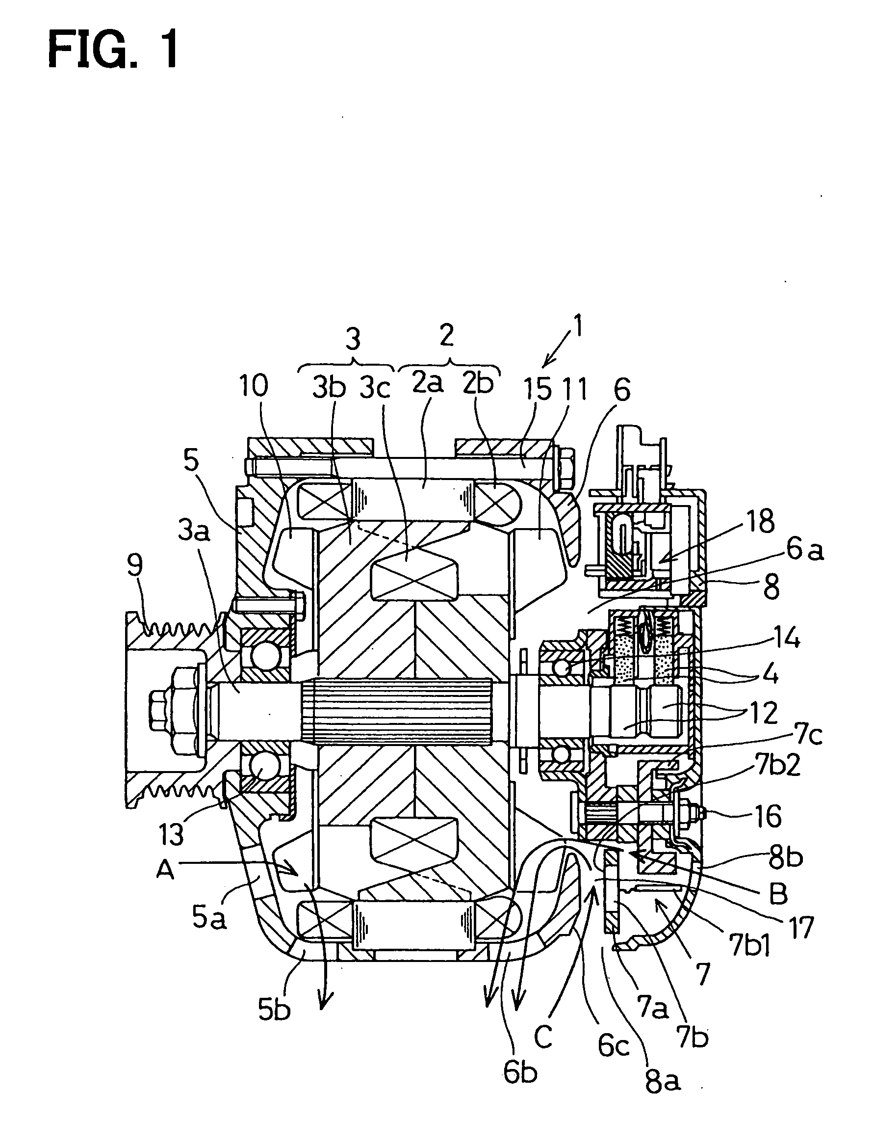
[0020] As shown in FIG. 1, an AC generator 1 for vehicle according to a first embodiment has a stator 2, a rotor 3, a brush 4, frames 5, 6, a rectifier 7 and a protection cover 8, which will be described below.
[0021] The stator 2 has a stator core 2a supported by the frames 5, 6, and an armature winding 2b winded on the stator 2. A rotation of the rotor 3 induces AC voltage in the armature winding 2b. For instance, the armature winding 2b has three armature coils, which are connected by a Y connection or by a delta connection.
[0022] The rotor 3 has a rotor shaft 3a to which a pulley 9 transmits a torque generated by an engine (not shown), a pair of pole cores (magnetic poles) 3b fixed onto the rotor shaft 3a and a field winding 3c wound on the pole cores 3b. The pulley 9 is fixed on one end portion of the rotor shaft 3a, and connected to a crankpulley (not shown) of the engine via a belt (not shown).
[0023] Cooling fans 10, 11 are respectively fixed to both axial end faces of the...
second embodiment
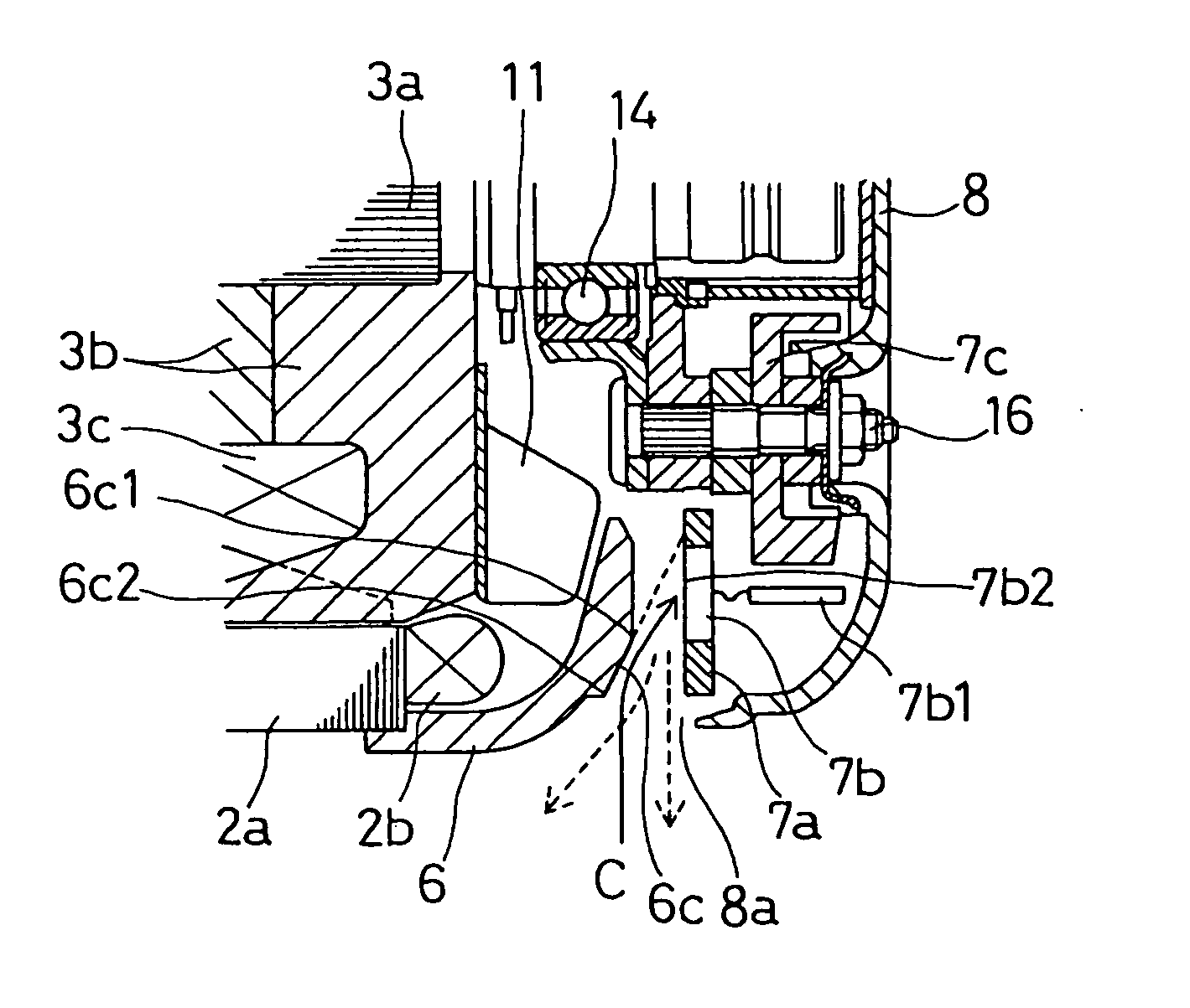
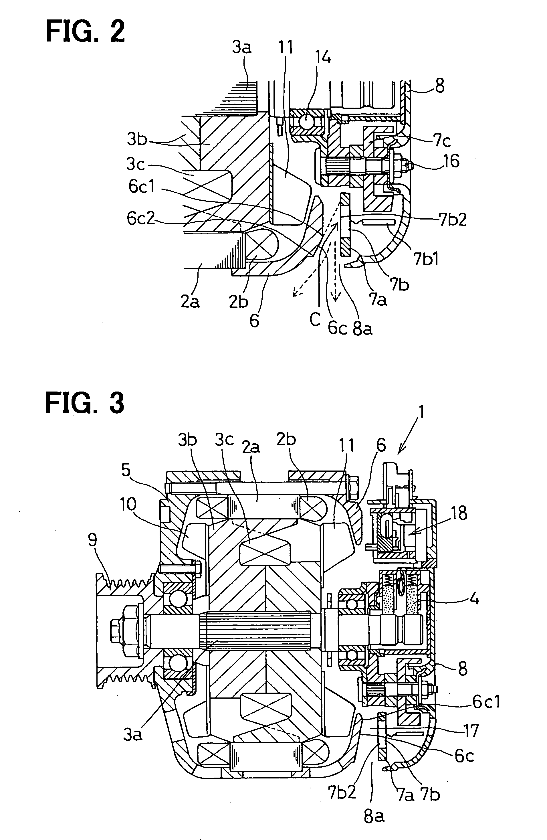
[0048] As shown in FIG. 3, an AC generator 1 according to a second embodiment is an example having a slant face 6c of which a start end 6c1 is radially inner side (upper side in FIG. 3) than the rectifier devices 7b.
[0049] According to this structure, a distance 17 between the slant face 6c and the rectifier devices 7b can be wide, so as not to stay muddy water and so on therein and to restrictcorrosion of a holder fin 7a (especially at a portion where the rectifier devices 7b is press-fitted therein) by salt water and so on. Further, the slant face 6c induces the cooling wind to hit on a bottom faces 7b2 of the rectifier devices 7b effectively, so as to improve a performance in cooling the rectifier devices 7b.
third embodiment
[0050] As shown in FIG. 4, an AC generator 1 according to a third embodiment has heat radiation ribs 19 on the holder fin 7a at negative electric potential.
[0051] As shown in FIG. 5, a number of the heat radiation ribs 19 are disposed on a face of the holder fin 7a at a side of the rear frame 6, so as to be in a radial direction of the holder fin 7a along the flowing direction of the cooling wind.
[0052] According to this structure, the heat radiation ribs 19 on the holder fin 7a increase the area for heat radiation of the holder fin 7a, so as to improve a heat radiation performance thereof. Further, the heat radiation ribs 19 forms discharge passages therebetween for discharging muddy water that intruded thereinto, so as to improve a performance more in discharging the muddy water, etc.
[0053] Further, the slant face 6c on the rear frame 6 induces the cooling wind C to hit on the bottom faces 7b2 of the rectifier devices 7b and to cool the rectifier devices 7b effectively, as same...
PUM
Abstract
An AC generator has negative pole-side rectifier devices press-fitted to a holder fin so as to dispose a bottom face of the rectifier device on a surface of the holder fin. The holder fin is disposed in such a manner that the bottom face of the rectifier device faces a rear frame of the AC generator. A clearance is formed between the rear frame and the bottom face through which the cooling wind for the rectifier device flows. The rear frame is provided with a slant face on its outer wall face for inducing the cooling wind introduced through an opening of the protection cover of the AC generator to the rectifier devices. Thus, the cooling wind induced by the slant face can hit on the bottom face of the rectifier devices directly, so as to cool the rectifier device well.
Description
CROSS REFERENCE TO RELATED APPLICATIONS [0001] This application is based upon and claims the benefit of priority of Japanese Patent Application No. 2004-94918 filed on Mar. 29, 2004, the contents of which are incorporated herein by reference. FIELD OF THE INVENTION [0002] The present invention relates to an AC generator for vehicles, especially relates to an AC generator targeting on an improvement of cooling performance for a rectifier located therein. BACKGROUND OF THE INVENTION [0003] Currently, a large power output is demanded for AC generator for vehicle, making a key issue in improving a cooling ability for a rectifier located therein, which generates a large amount of heat by a large current flowing therethrough. It is considered to raise an ability of fans for cooling the rectifier, however, this increases a noise of the fans. Thus, to secure a vehicular compartment against noise, it is not always appropriate to raise the cooling ability of the fans. [0004] JP-2001-037142-A ...
Claims
Application Information
Patent Timeline
Application Date:The date an application was filed.
Publication Date:The date a patent or application was officially published.
First Publication Date:The earliest publication date of a patent with the same application number.
Issue Date:Publication date of the patent grant document.
PCT Entry Date:The Entry date of PCT National Phase.
Estimated Expiry Date:The statutory expiry date of a patent right according to the Patent Law, and it is the longest term of protection that the patent right can achieve without the termination of the patent right due to other reasons(Term extension factor has been taken into account ).
Invalid Date:Actual expiry date is based on effective date or publication date of legal transaction data of invalid patent.

