Supercharge Your Innovation With Domain-Expert AI Agents!

Motorized hose reel with Anti-rotation interlock

Active Publication Date: 2015-05-14
COXWELLS
View PDF7 Cites 7 Cited by
  • Summary
  • Abstract
  • Description
  • Claims
  • Application Information

AI Technical Summary

Benefits of technology

The present invention is a motorized hose reel with a positive locking mechanism. The locking pin can be moved to three positions: a spool is locked, it is engaged with the hose reel spool to prevent rotating, it is engaged with a track to hold it away from the spool, and it closes an electrical switch to the motor. The mechanism that closes the electrical switch is an integral part of the locking pin, so the user is prevented from accidentally engaging the motor without first disengaging the locking pin. The invention can be applied to storage devices for hoses or other elongate members such as cables or rope.

Problems solved by technology

Since the mechanism that closes the electrical switch to the drive motor is an integral part of the locking pin, it is impossible for a user to accidentally engage the motor without first disengaging the locking pin.

Method used


Image

  • Motorized hose reel with Anti-rotation interlock
  • Motorized hose reel with Anti-rotation interlock
  • Motorized hose reel with Anti-rotation interlock

Examples


Embodiment Construction

[0012]The drawing figures are intended to illustrate the general manner of construction and are not necessarily to scale. In the detailed description and in the drawing figures, specific illustrative examples are shown and herein described in detail. It should be understood, however, that the drawing figures and detailed description are not intended to limit the invention to the particular form disclosed, but are merely illustrative and intended to teach one of ordinary skill how to make and / or use the invention claimed herein and for setting forth the best mode for carrying out the invention.

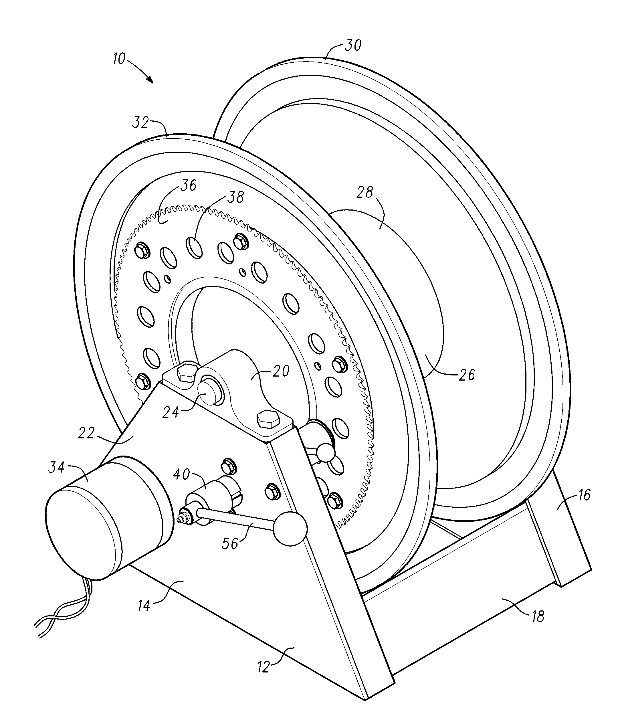
[0013]With reference to FIG. 1, a reel assembly 10 having an anti-rotation interlock mechanism incorporating features of the present invention comprises a frame 12 composed of a right side plate 14, a left side plate 16, and a center support section 18. A right side pillow block housing 20 is attached to the upper end 22 of right side plate 14. A left side pillow block housing (not shown) is si...


PUM


Abstract

A motorized hose reel with a positive locking mechanism includes a spool that is rotatably supported by a support frame, a motor in driving communication with the spool and a locking pin. The locking pin is movable to any one of three positions. In the first position, a spring forces the locking pin to engage a corresponding aperture in the hose reel spool. As the locking pin is rotated, a shaft extending radially from the locking pin engages a track formed in the housing. This causes the locking pin to withdraw from the hose reel spool against the force of the spring. Further rotation of the locking pin causes the radially-extending shaft to engage a detent, which holds the locking pin away from the hose reel spool. Still further rotation of the locking pin causes the radially-extending shaft to close a switch, which completes an electrical circuit to the motor.

Description

BACKGROUND OF THE INVENTION[0001]This invention relates generally to take-up reels of the type used for winding, and paying-out flexible elongated members such as hoses and electrical cables and, in particular, to motorized take-up reels.[0002]It is well known in the art to provide an apparatus wherein an elongate flexible member such as a cable, rope, hose, electrical cord or the like is wound about a take-up reel for storage when not in use, and which is paid out by unwinding from the take-up reel to the appropriate length as required. A popular application for this arrangement is use of a flexible hose for carrying air, water, oil, grease, or the like from a reservoir to a dispensing nozzle. For example, in a typical mobile Liquefied Petroleum (LP) gas delivery truck, LP gas is delivered from a pressurized tank to a take-up reel which stores a length of tubular hose. When LP gas is to be delivered, the hose is pulled from the reel until the desired length is paid out. When the ho...

Claims


Application Information

Patent Timeline
IPC IPC(8): B65H75/30B65H75/44
CPCB65H75/4428B65H75/30B65H75/4486
Inventor KUCERA, JOHN G.
Owner COXWELLS
Features
  • R&D
  • Intellectual Property
  • Life Sciences
  • Materials
  • Tech Scout
  • Unparalleled Data Quality
  • Higher Quality Content
  • 60% Fewer Hallucinations
Learn More