Patient support guard structure

a guard structure and patient technology, applied in the field of patient supports, can solve the problems of inconvenience in operating the patient support, limited unlocking of the side rail locking mechanism, and difficulty in allowing patients to exit the bed

Active Publication Date: 2015-06-18
STRYKER CORP
View PDF6 Cites 45 Cited by
  • Summary
  • Abstract
  • Description
  • Claims
  • Application Information

AI Technical Summary

Benefits of technology

[0007]A guard structure of a patient support includes a locking structure that is mechanically unlockable. A release for the locking structure may be positioned to be accessible to an occupant of the patient support. The release may include an access port that may be opened. The locking structure may additionally or alternatively be electrically unlockable. The release may include a button that electrically unlocks the guard structure. A solenoid may be used to electrically unlock the guard structure and may optionally be coupled with a locking structure that mechanically maintains the guard structure in an unlocked state. One or more guard structures may automatically unlock during a CPR emergency. A maximum or minimum allowable height of the patient support may be adjusted based on a sensed locked state and / or a sensed position of the guard structure. Other aspects of the guard structure are also disclosed.

Problems solved by technology

Side rail locking mechanisms are limited in how they can be unlocked.
This may lead to inconvenience when operating the patient support.
For example, typical locking structures or locking mechanisms are operable only from outside the patient support or bed by a caregiver or attendant; this makes it difficult for patients to exit the bed once the rails have been raised without calling for help.
This may be inconvenient in some situations, for example when a patient needs to quickly use a restroom or in maternity wards where an infant is present in the bed along with the patient.
In addition, during a medical emergency, this may be dangerous if patient access is required quickly and the each rail needs to be manually unlocked by an attendant.
This may be dangerous to the occupant of the patient support, due to the danger of falling out of the bed, or may damage side rails due to impact with the floor when the bed is lowered.

Method used


Image

  • Patient support guard structure
  • Patient support guard structure
  • Patient support guard structure

Examples


Embodiment Construction

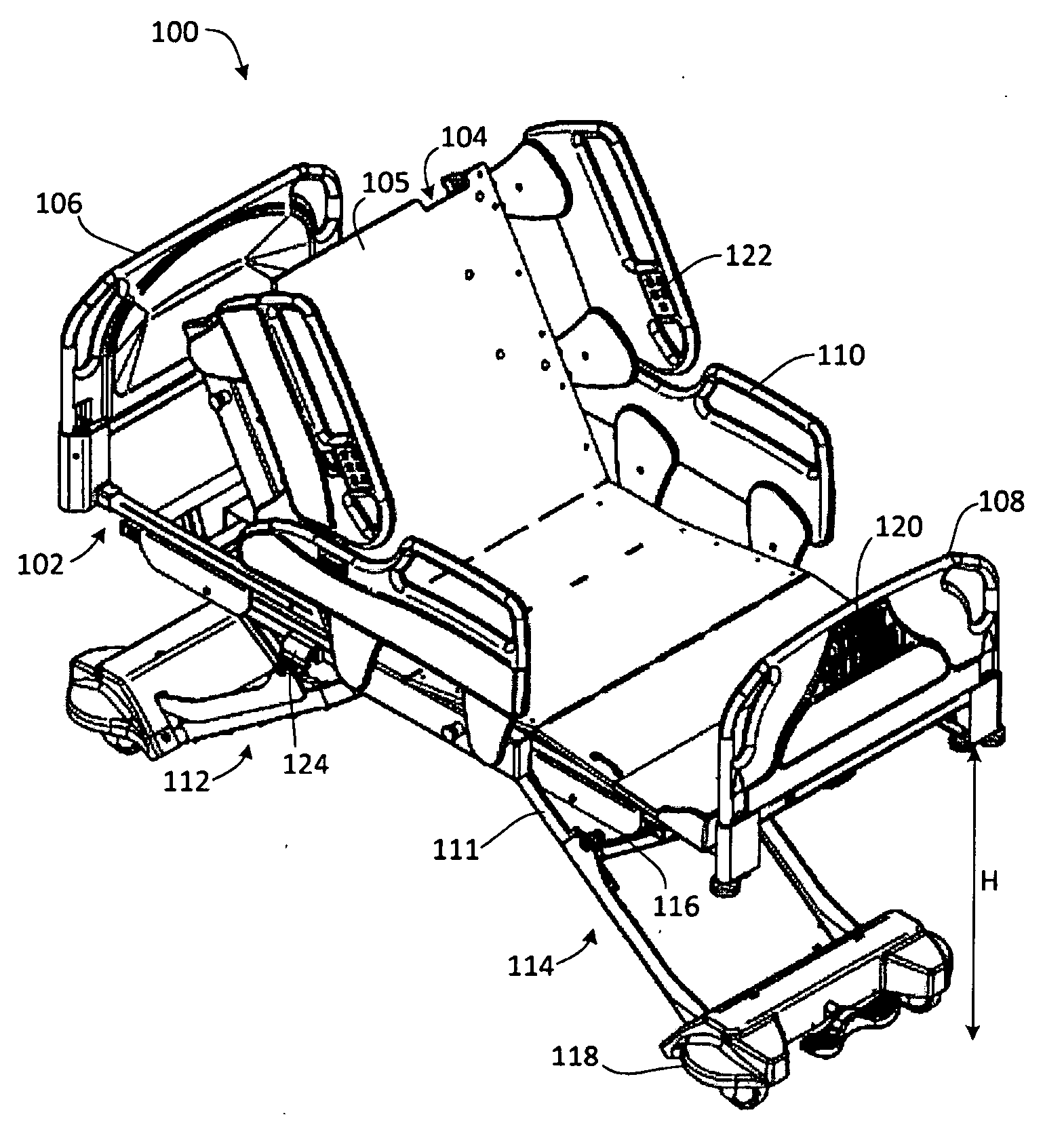
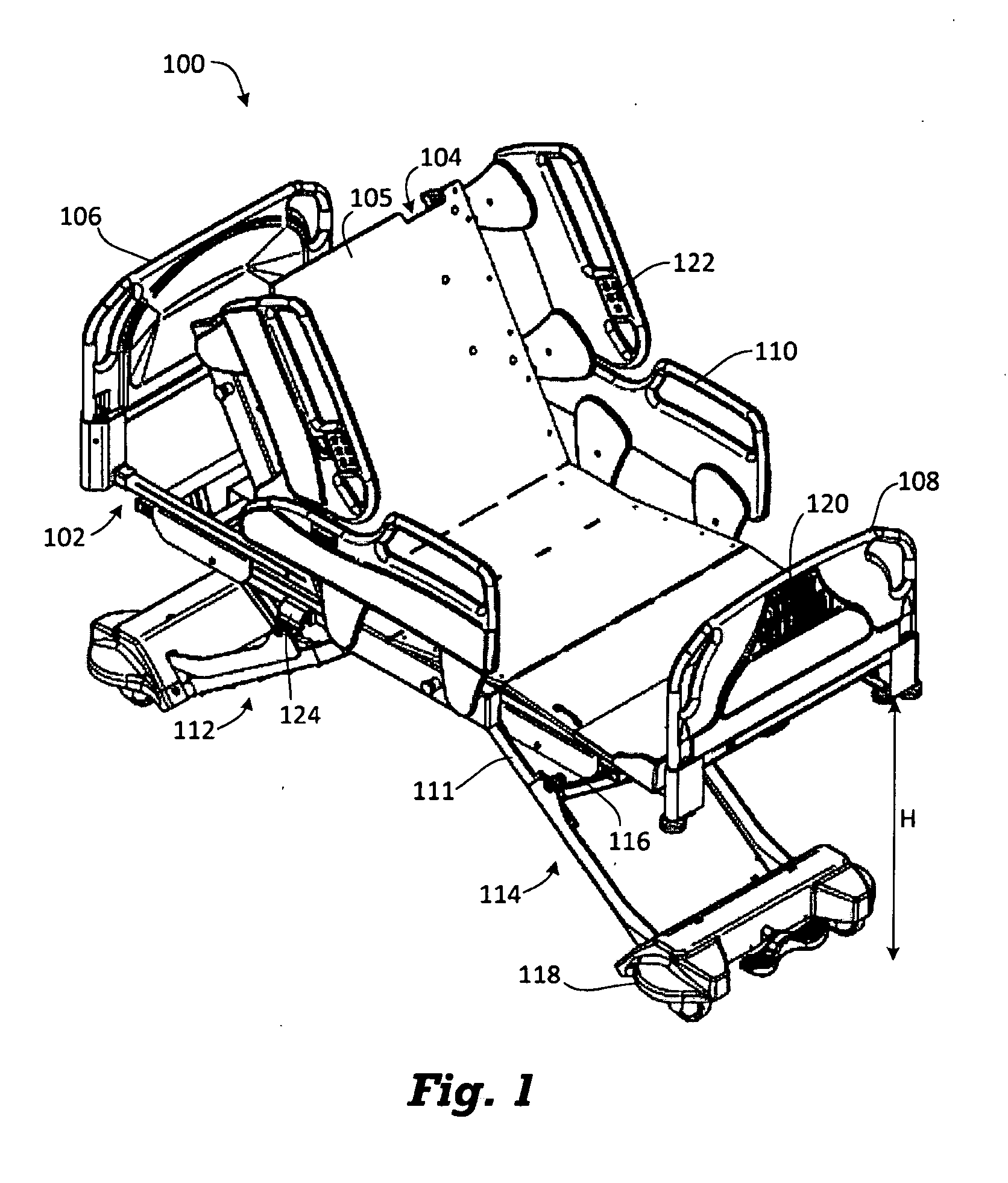
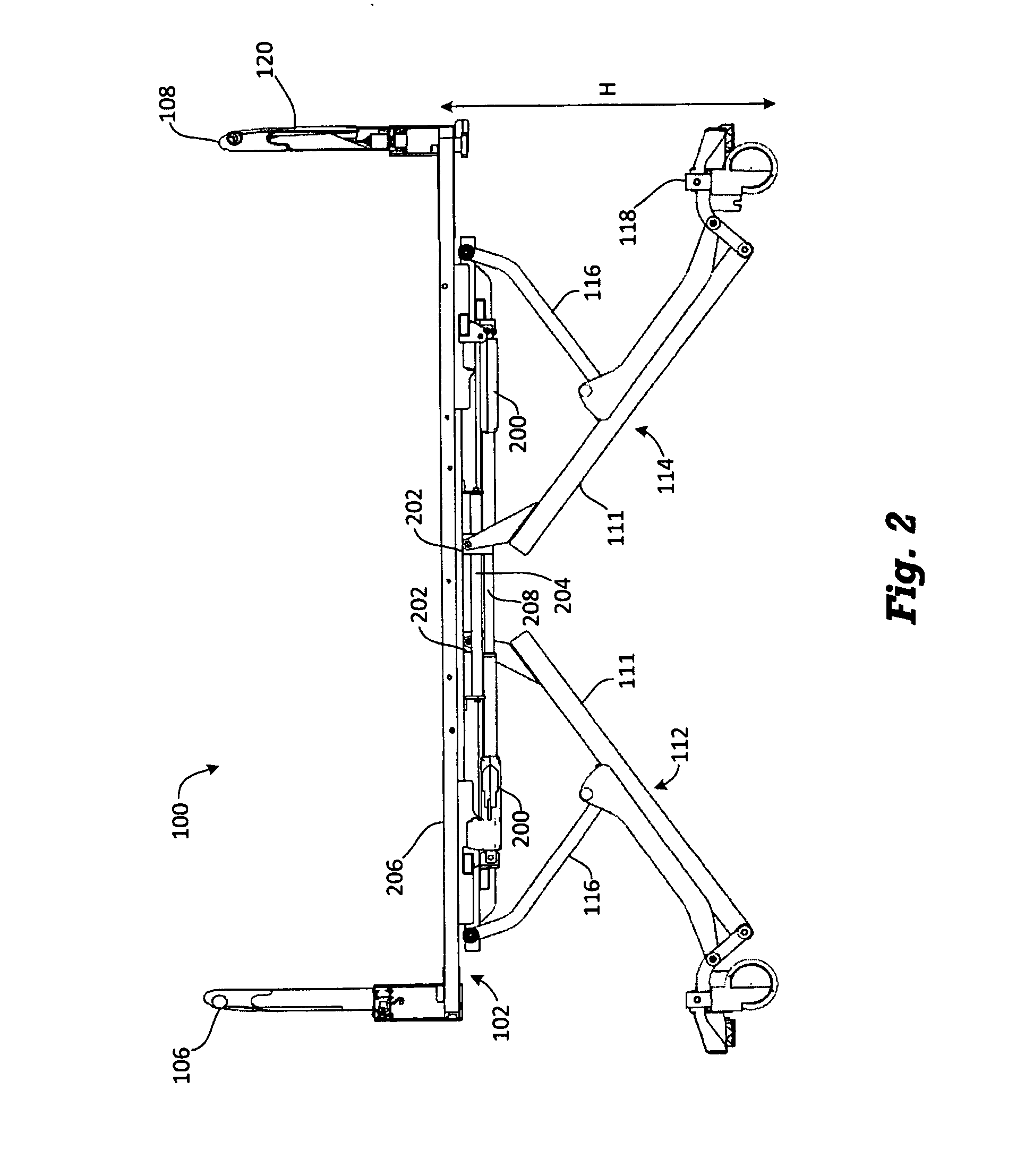
[0021]As used herein, the term “patient support” refers to an apparatus for supporting a patient in an elevated position relative to a support surface for the apparatus, such as a floor. One embodiment of a patient support includes beds, for example hospital beds for use in supporting patients in a hospital environment. Other embodiments may be conceived by those skilled in the art. The exemplary term “hospital bed” or simply “bed” may be used interchangeably with “patient support” herein without limiting the generality of the disclosure.

[0022]As used herein, the term “guard structure” refers to an apparatus mountable to or integral with a patient support that prevents or interferes with egress of an occupant of the patient support from the patient support, particularly egress in an unintended manner. Guard structures are often movable to selectively permit egress of an occupant of the patient support and are usually located about the periphery of the bed, for example on a side of t...


PUM


Abstract

A guard structure of a patient support, such as a hospital bed, is electrically unlockable. An electromechanical actuator, such as a solenoid, may be used to electrically unlock the guard structure. The guard structure may also be mechanically unlockable. The guard structure may automatically unlock during a CPR emergency. A maximum allowable height of the patient support may be adjusted based on a sensed locked state or position of the guard structure. A release for the guard structure may be positioned to be accessible to an occupant of the patient support. The release may include an access port that may be opened. The release may include a button that electrically unlocks the guard structure.

Description

CROSS-REFERENCE TO RELATED APPLICATIONS[0001]This application is a §371 national entry of PCT / CA2012 / 000354, filed Apr. 12, 2013, which claims the benefit of U.S. patent application 61 / 623,559, filed Apr. 12, 2012, the entirety of which are incorporated herein by reference.FIELD OF THE INVENTION[0002]This disclosure relates to patient supports, such as hospital beds, and more specifically, patient supports having a movable guard structure, such as a side rail.BACKGROUND[0003]Patient supports, such as hospital beds, are known to have guard structures, such as side rails, that are movable to permit patient entry and egress from the patient support; for example, they may be raised and lowered. Side rails are known to be mechanically lockable. When a typical side rail is locked, it cannot be moved.[0004]Side rail locking mechanisms are limited in how they can be unlocked. This may lead to inconvenience when operating the patient support. For example, typical locking structures or lockin...

Claims


Application Information

Patent Timeline
Patent Type & Authority Applications(United States)
IPC IPC(8): A61G7/05
CPCA61G7/0507A61G2007/0524A61G2007/0516A61G7/005A61G7/015A61G7/018A61G7/0509A61G7/0514A61G7/052A61G7/0524A61G7/0516
Inventor ROUSSY, RICHARD B.CONNELL, JASONGEORGE, CHRISTOPHERJACOB, CHRISTOPHER
Owner STRYKER CORP
Why Eureka
Try Eureka