Pump, motor and assembly for beneficial agent delivery

Pending Publication Date: 2015-07-02
ABBVIE INC
View PDF13 Cites 16 Cited by
  • Summary
  • Abstract
  • Description
  • Claims
  • Application Information

AI Technical Summary

Benefits of technology

[0030]According to another aspect of the disclosed subject matter, and further to the above, a device for delivery of a beneficial agent to a user generally includes a cassette, a delivery tube, a pump, a lock member, and a contact force sensor. The cassette includes a cassette housing with a fluid reservoir defined therein. The cassette housing has a cassette base region. The delivery tube is fluidly coupled with the fluid reservoir. The pump includes a pump housing containing a pump assembly having a fluid drive component, the pump housing having a receiving region to receive the cassette base region, the fluid drive component disposed proximate the receiving region. The lock member is coupled to the pump housing and movable between an open position and a closed position, the cassette capable of being inserted into and removed from the receiving region when the lock member is in the open position, and the cassette being secured to the pump with the cassette base region within the receiving region and a length of the delivery tube in operative engagement with the fluid drive component when the lock member is in the closed position. The lock member includes a proximity tag configured to be disposed proximate the proximity sensor when the lock member is in the closed position. The contact force sensor is in communication with the delivery tube and arranged to measure a force or pressure in the delivery tube. The device further includes one or more processors in communication with the proximity sensor and the contact force sensor to receive a proximity signal and contact force data, respectively, therefrom, the one or more processors configured to determine whether the lock member is in the closed position using the proximity signal, determine whether the delivery tube is in operative engagement with the fluid drive component using the contact force data; and enable operation of the fluid drive component if the lock member is determined to be in the closed position and the delivery tube is determined to be in operative engagement with the fluid drive component.
[0031]Additionally, and as embodied herein, the proximity sensor can include a reed switch. The proximity tag can include a magnet. The one or more processors can be further configured to compare the contact force data to a threshold value, and determine the delivery tube is in operative engagement with the fluid drive component if the contact force data exceeds the threshold value. The one or more processors can be further configured to determine a local minimum force value detected by the contact force sensor during each revolution of each pumping cycle, and determine the delivery tube is in operative engagement with the fluid drive component if the local minimum force value exceeds the local maximum force value of a corresponding pump cycle by a local minimum threshold amount.
[0032]Furthermore, and as embodied herein, a cassette base region can include a RFID tag. The receiving region can include a RFID reader configured to read the RFID tag when the cassette is secured to the pump. The one or more processors can be further configured to receive identification information for the cassette encoded on the RFID tag from the RFID reader, determine whether the identification information is valid, and enable operation of the fluid drive component if the identification information is valid. The RFID tag can further include an expiration date of the beneficial agent, and the one or more processors can be further configured to receive the expiration date of the beneficial agent from the RFID reader, determine whether the expiration date is excee

Problems solved by technology

The error can include a mechanical failure of the fluid drive comp

Method used


Image

  • Pump, motor and assembly for beneficial agent delivery
  • Pump, motor and assembly for beneficial agent delivery
  • Pump, motor and assembly for beneficial agent delivery

Examples


Example

[0088]Reference will now be made in detail to the various exemplary embodiments of the disclosed subject matter, exemplary embodiments of which are illustrated in the accompanying drawings. The structure and corresponding method of operation of and method of using the disclosed subject matter will be described in conjunction with the detailed description of the system.

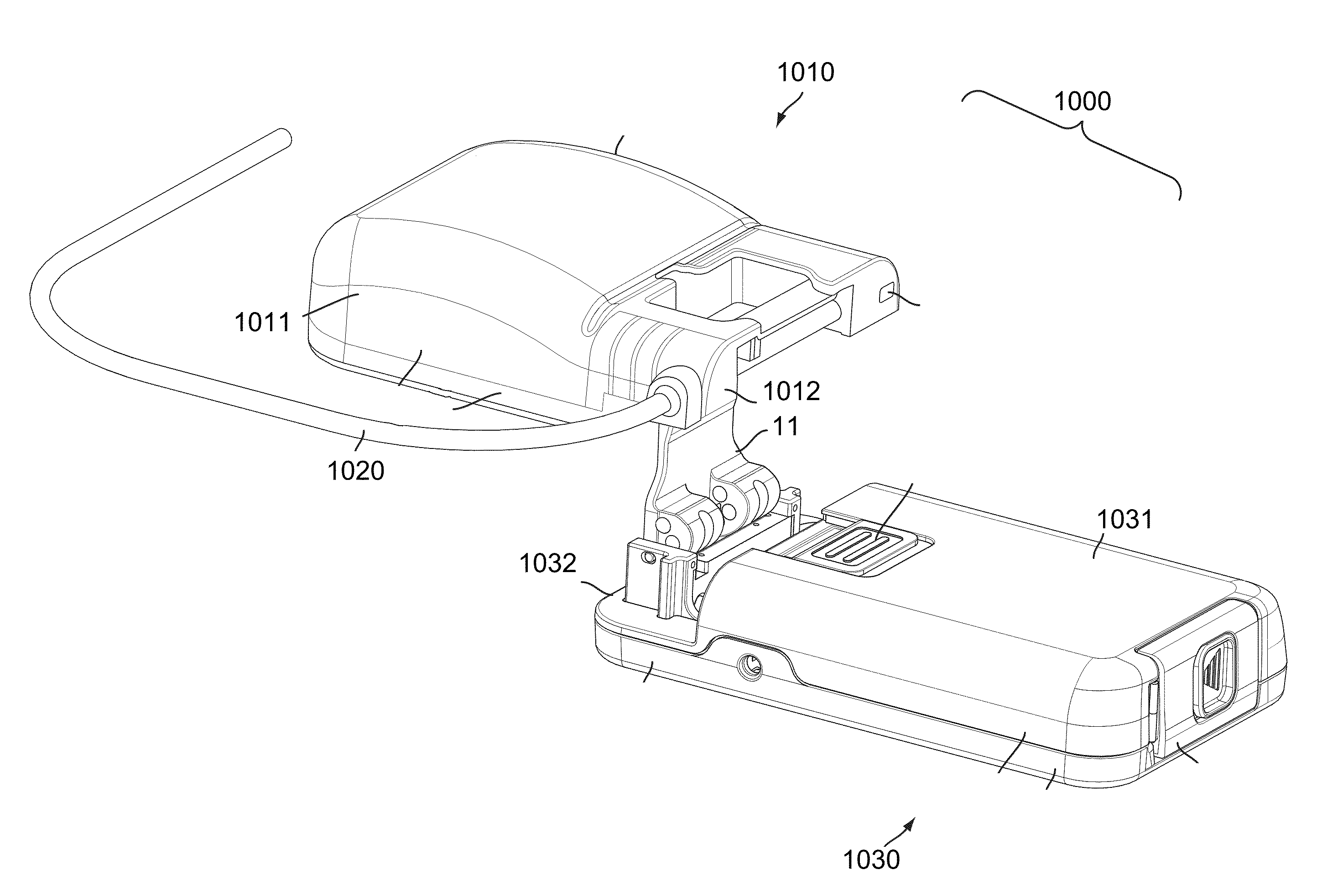
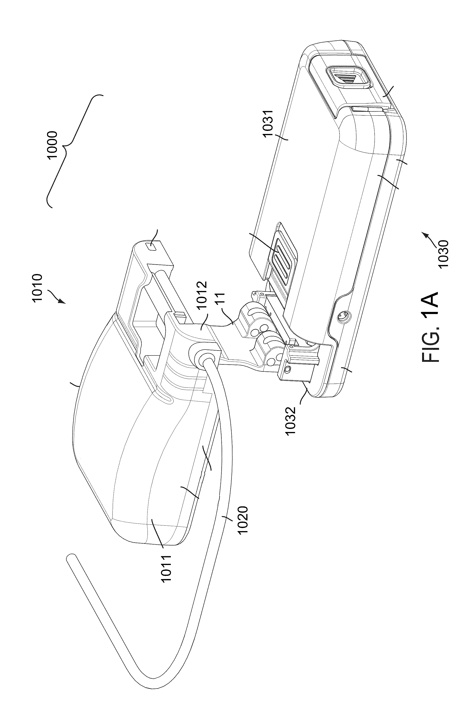
[0089]The apparatus and methods presented herein can be used for administering any of a variety of suitable therapeutic agents or substances, such as a drug or biologic agent, to a patient. For example, and as embodied herein, the device can include a pump joined to a cassette, which can include a fluid reservoir containing a fluid substance and can be joined to a delivery tube system. In operation, the pump can operate on the cassette to deliver the fluid substance through the tubing system. In this manner, the device is capable of administering a dosage of the fluid substance, such as a therapeutic agent, including a...


PUM


Abstract

Device for delivering a beneficial agent to a user includes a cassette including a cassette housing with a fluid reservoir, the cassette housing having a cassette base region, and a delivery tube. The device also includes a pump having a pump housing containing a pump assembly and having a receiving region to receive the cassette base region. The pump assembly includes a fluid drive component, a display, a plurality of input buttons. The pump assembly also includes a first processor coupled to the fluid drive component and the display and configured to reduce power to the fluid drive component and the display when the pump is in an inactive state, and a second processor coupled to the first processor and the plurality of input buttons, the second processor configured to provide an activation signal to the first processor when one or more of the plurality of input buttons is deployed.

Description

CROSS-REFERENCE TO RELATED APPLICATIONS[0001]This application claims priority to U.S. Provisional Patent Application Nos. 61 / 922,709, filed Dec. 31, 2013; and 62 / 054,134, filed Sep. 23, 2014; each of which is incorporated by reference herein in its entirety.BACKGROUND[0002]1. Field of the Disclosed Subject Matter[0003]The disclosed subject matter is generally related to devices, systems and methods for controlling and delivering fluids, for example for delivery of a beneficial agent to a user.[0004]2. Description of Related Art[0005]A variety of fluid transport devices and systems have been developed for controlling and delivering beneficial agents in fluid form. Such fluid flow systems can include 1) volumetric-based aspiration flow systems using positive displacement pumps, and 2) vacuum-based aspiration systems using a vacuum source. For example, volumetric aspiration systems include peristaltic pumps for the delivery of therapeutic agents to a user. Various forms of peristaltic ...

Claims


Application Information

Patent Timeline
IPC IPC(8): A61M5/168A61M5/142
CPCA61M5/16831A61M5/14228A61M5/14244A61M2005/14208A61M2205/60A61M2005/16868A61M2005/16872A61M2205/12A61M2205/50A61M2005/16863A61M2205/6054F04B43/082A61M2205/14A61M2205/16A61M5/142F04B43/12A61M2205/502F04B43/1223
Inventor PANZER, MARK
Owner ABBVIE INC
Why Eureka
Try Eureka