Apparatus and a method of generating bubbles and foams

Inactive Publication Date: 2015-07-09
KONINKLJIJKE PHILIPS NV
View PDF0 Cites 0 Cited by
  • Summary
  • Abstract
  • Description
  • Claims
  • Application Information

AI Technical Summary

Benefits of technology

[0006]Comparing to liquid without bubbles inside, foam is easier to daub and has better penetrability. The difference in the penetrability is illustrated in FIGS. 1a and 1b. Referring to FIG. 1a, surface tension of the liquid holds the molecules together, resulting in larger droplets 10, which limits a total contact area between the liquid and a surface 12 and limits an absorption 14 into the surface 12. The flowability of water also decreases a duration of a contact betw

Problems solved by technology

Therefore a user could not easily adapt an apparatus to generate bubbles with c

Method used


Image

  • Apparatus and a method of generating bubbles and foams
  • Apparatus and a method of generating bubbles and foams
  • Apparatus and a method of generating bubbles and foams

Examples


first embodiment

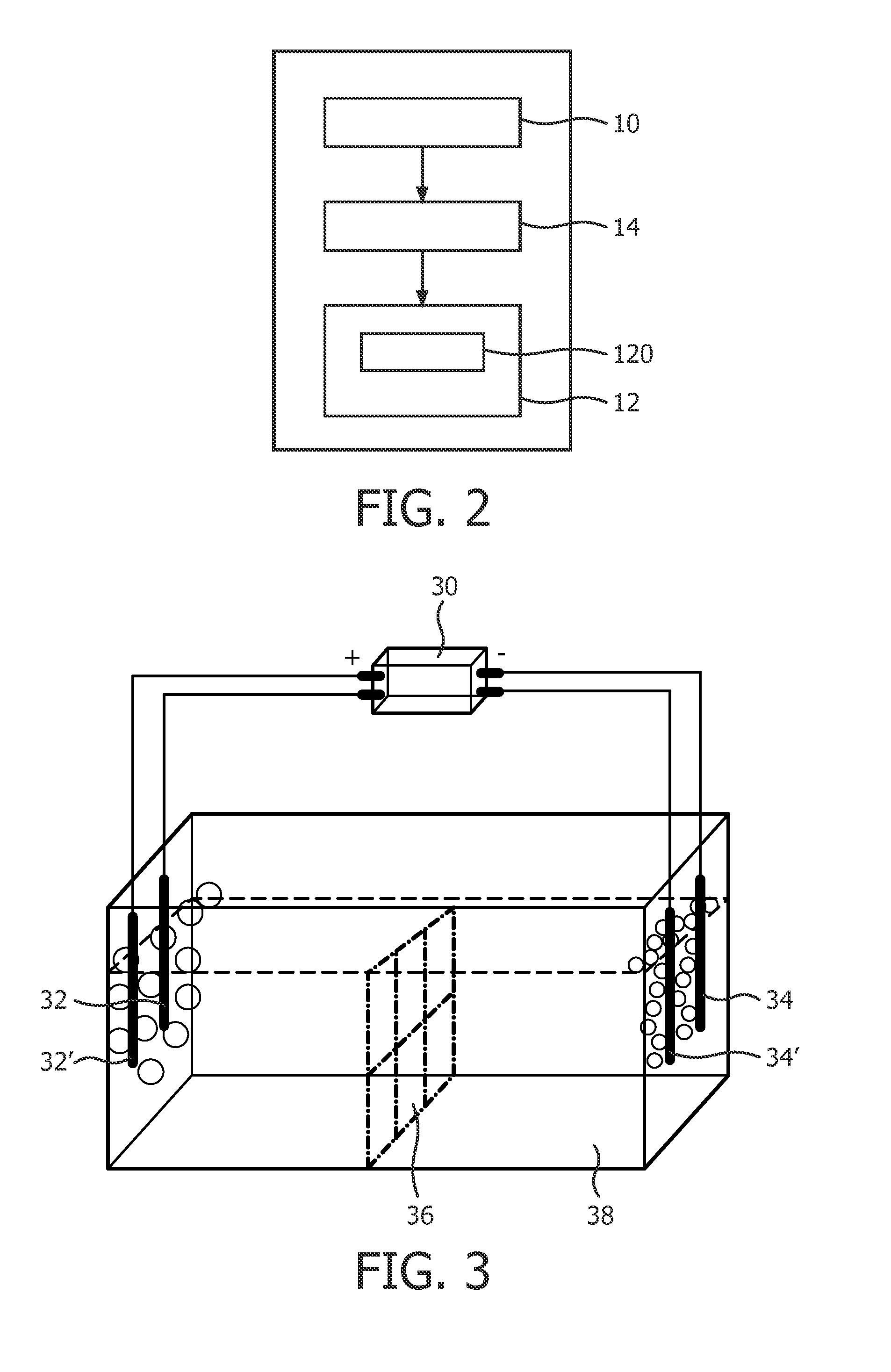
[0102]In a first embodiment, as shown in FIG. 4, the controller 14 applies electricity through one inert anode 32 and one inert cathode 34 or metal cathode 34′. Gas G1 is generated at the anode 32, and gas G2 is generated at the cathode 34. In one example, neural water is used as the electrolyte, and the gas G1 is oxygen O2 and gas G2 is hydrogen H2. The electrolysis equation on the anode is:

2H2O−4e−→4H++O2.

[0103]And the electrolysis equation on the cathode is:

2H2O+2e−→H2+2OH−.

[0104]In this example, the water is added with a surfactant, thus the foam enriched with O2 is formed from the bubbles on a surface of the water at the anode 32, and the foam enriched with H2 is formed from the bubbles on a surface of the water at the cathode 34. In one embodiment, the apparatus further comprises a separator 36 between the anode 32 and the cathode 34 for avoiding the two foams mixed. If the foams are required to be mixed, the separator 36 can be removed.

second embodiment

[0105]In a second embodiment, as shown in FIG. 5, the controller 14 applies electricity through one active metal anode 32′ and one inert cathode 34 or one metal cathode 34′. Gas G2 could be generated on the cathode. On the anode, the active metal will lose electron and release metal ions. Thus there is no gas generated on the anode 32′. The active metal should be more active than hydrogen. According to the chemical activity, K>Ca>Na>Mg>Al>Zn>Fe(>H)>Cu>Pt>Au. Thus an active metal anode made from Al, Zn and Fe can be used. The electrolyte filled in container could be water or an acid solution. For example, using Fe as electrode, the electrolyte is with acidity, and the electrolysis would only generate H2 gas on the cathode 34, while Fe3+ would be generated on the anode 32′.

[0106]The electrolysis equation on the anode is:

Fe−3e−→Fe3+.

[0107]And the electrolysis equation on the cathode is:

2H++2e−→H2.

third embodiment

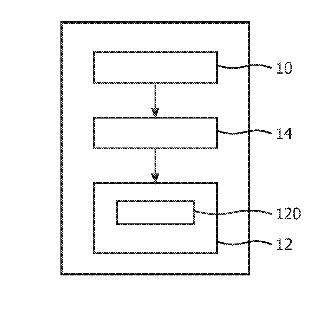
[0108]In a third embodiment, the anode or cathode is with the material which has Double Electric Layer Capacity character such an activated carbon. As shown in FIG. 6a, the controller 14 applies electricity through one inert anode 32 and cathode 34″ with double electric layer capacity. The cathode 34″ with double electric layer capacity will adsorb ions in water, therefore the reaction that gas should have been generated on the cathode would stop. In FIG. 6a, only gas G1 could be generated on the anode 32. In a varied embodiment, the controller 14 applies electricity through one anode 32″ with double electric layer capacity and one inert cathode 34 or metal cathode 34′. In this embodiment, only gas G2 will be generated on the cathode, as shown in FIG. 6b.

[0109]In another embodiment, the electrolyzer 120 comprises at least two anodes in different sizes and / or shapes, and / or at least two cathodes in different sizes and / or shapes, the first unit determines an mount of gas in each bubb...


PUM

PropertyMeasurementUnit
Sizeaaaaaaaaaa
Flexibilityaaaaaaaaaa
Currentaaaaaaaaaa

Abstract

The prior arts generate bubbles with fixed characteristics of the gas in the bubbles. The invention proposes an apparatus of generating bubbles and a method thereof. The apparatus comprising: a first unit (10) configured to determine at least one characteristic of a gas in the bubbles; a second unit (12) configured to generate the bubbles, comprising: an electrolyzer (120) configured to electrolyze an electrolyte to generate the gas in the electrolyte, thereby generating bubbles; and a controller (14), configured to control the second unit to generate the bubbles according to the at least one characteristic of the gas. In embodiments of the invention, the generation is controllable with respect to the gas in the bubble based on the practical requirement of the gas, and is more flexible and with wide applicability.

Description

TECHNICAL FIELD[0001]The disclosure relates to generations of bubbles and foams containing the bubbles, particularly to generations of bubbles via generating gas.BACKGROUND ART[0002]Foam is generally formed by trapping a great number of gaseous bubbles in a liquid and widely used in people's daily life, for example, in shaving, surface cleaning, etc.[0003]Generally, bubbles are generated and then subject to a surface activation process which reduce surface tension of the liquid so as to prevent the bubbles from breaking[0004]One popular method of generating bubbles is called mechanical rabbling. Specifically, air and liquid are mixed by mechanical rabbling to generate bubbles. Other methods include gas pumping, heating, etc.[0005]However, the above methods of generating bubbles in order to generate foams are usually for industrial applications and have their own disadvantages such as high cost, high complexity and low controllability.SUMMARY OF THE INVENTION[0006]Comparing to liquid...

Claims


Application Information

Patent Timeline
IPC IPC(8): C25B15/02B01F3/04C25B1/02C25B9/10C25B9/17C25B9/23
CPCC25B15/02C25B9/10B01F3/04106B01F2003/04914B01F3/04439C25B1/02B01F3/04446C25B1/04C25B1/13C25B1/30C25B15/08Y02E60/36C25B9/17C25B9/23C02F1/465C25B9/00B01F23/231B01F23/235B01F23/2319B01F23/23764
Inventor HU, PEIXINWANG, GUANGWEIJIN, JIANYU
Owner KONINKLJIJKE PHILIPS NV
Why Eureka
Try Eureka