Ink jet printer and printing method

a printing method and printer technology, applied in printing, duplicating/marking methods, textiles and paper, etc., can solve the problems of medium damage or discoloration, and achieve the effect of suppressing at least one of damage and discoloration of a medium

Active Publication Date: 2015-07-23
SEIKO EPSON CORP
View PDF5 Cites 12 Cited by
  • Summary
  • Abstract
  • Description
  • Claims
  • Application Information

AI Technical Summary

Benefits of technology

[0010]An advantage of some aspects of the invention is to provide an ink jet printer and a printing method which are capable of suppressing at least one of damage and discoloration of a medium when performing surface modification of the medium by plasma irradiation.

Problems solved by technology

However, in the surface treatment performed through the direct method, since a discharge portion directly comes in contact with the medium, the medium is likely to be damaged or discolored.

Method used


Image

  • Ink jet printer and printing method
  • Ink jet printer and printing method
  • Ink jet printer and printing method

Examples


first embodiment

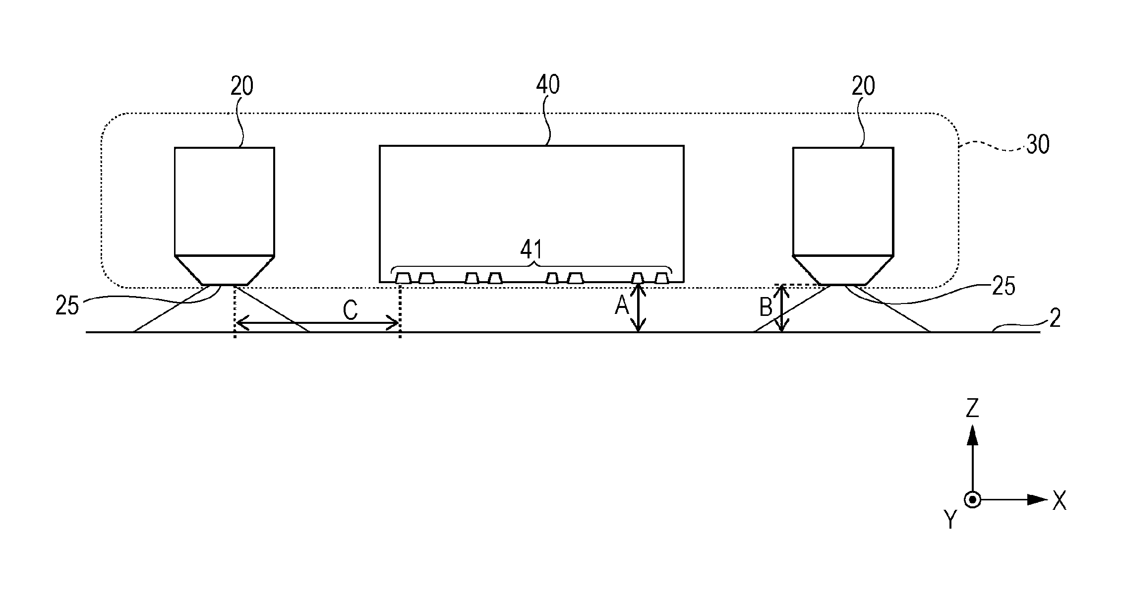
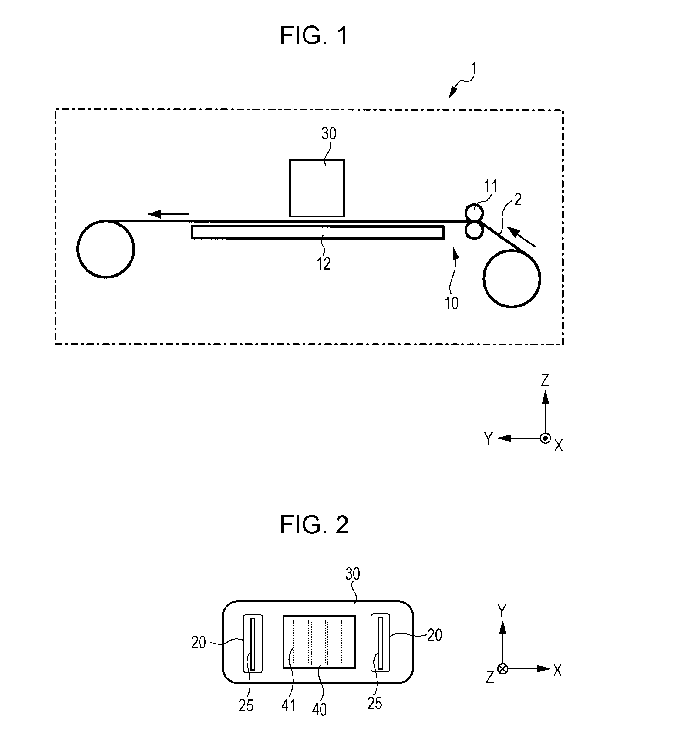
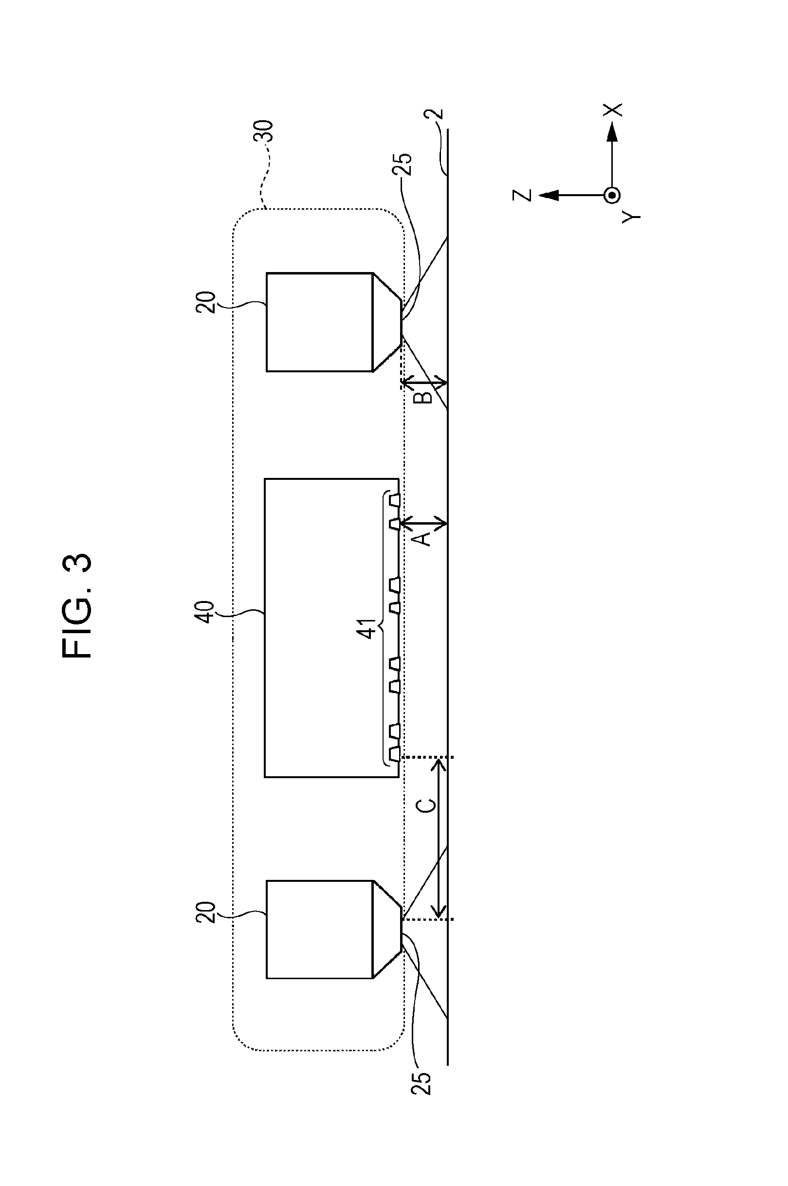
[0028]Hereinafter, embodiments of the invention will be described in detail. It should be noted that the invention is not limited to the following embodiments, and can include various types of modifications which are carried out within the scope of the invention. In the following description, three directions which are orthogonal to each other are respectively referred to as an X direction, a Y direction, and a Z direction. In addition, the Z direction is a vertical direction, and the Y direction is a direction in which the medium is transported. The upper side of the vertical direction is a +Z direction, and the lower side thereof is a −Z direction. Three directions corresponding to these directions are illustrated in the drawings as well. Ink jet printer

[0029]FIG. 1 is a diagram schematically illustrating an ink jet printer according to the embodiment. The ink jet printer 1 includes a transport mechanism 10 which transports a medium 2 in the Y direction (the first direction), and ...

second embodiment

[0113]In the first embodiment, the plasma irradiation mechanism 20 is provided on both sides of the head 40; however, in the second embodiment, the plasma irradiation mechanism 20 is provided on only one side of the head 40. Hereinafter, regarding an ink jet printer and a printing method according to the second embodiment, the description will focus on the differences from the first embodiment. Other points which are not particularly described are the same as in the first embodiment. In addition, in FIGS. 6 and 7, the same constituent elements as in the first embodiment are given the same reference numerals which are used in FIGS. 1 to 5.

Ink Jet Printer

[0114]FIG. 6 is a bottom view schematically illustrating the configuration of a carriage 30 in an ink jet printer 1 according to a second embodiment of the invention. As illustrated in FIG. 6, the plasma irradiation mechanism 20 (20B) is provided on one side of the head 40 in the X direction. The plasma irradiation mechanism 20B is, f...

third embodiment

[0119]In the first and second embodiments, the line-type plasma irradiation mechanism is employed as the plasma irradiation mechanism, while the spot-type plasma irradiation mechanism is employed in the third embodiment. Hereinafter, regarding an ink jet printer and a printing method according to the third embodiment, the description will focus on the differences from the first embodiment. Other points which are not particularly described are the same as in the first embodiment. In addition, in FIG. 8, the same constituent elements as in the first embodiment are given the same reference numerals which are used in FIGS. 1 to 5.

[0120]FIG. 8 is a bottom view schematically illustrating the configuration of a carriage 30 in an ink jet printer according to a third embodiment of the invention. As illustrated in FIG. 8, two plasma irradiation mechanisms 20a are disposed on one side of the head 40. The two plasma irradiation mechanisms 20a are disposed along the transporting direction (Y) of...


PUM

PropertyMeasurementUnit
distanceaaaaaaaaaa
distanceaaaaaaaaaa
distanceaaaaaaaaaa

Abstract

An ink jet printer includes a transport mechanism that transports a medium in a first direction; and a carriage that includes a plasma irradiation mechanism, which emits plasma generated in a discharge portion from a plasma irradiation port and then irradiates at least a part of the medium with the plasma, and a head which ejects ink onto the part of the medium which is irradiated with the plasma, and that moves in a second direction intersecting with the first direction, in which the plasma irradiation mechanism is provided on one side of the head in the second direction, and the discharge portion of the plasma irradiation mechanism is disposed so as not to come in contact with the medium.

Description

BACKGROUND[0001]1. Technical Field[0002]The present invention relates to an ink jet printer and a printing method.[0003]2. Related Art[0004]In the related art, a printing method using an ink jet printer is performed by causing small ink droplets to be scattered and then attached onto a medium such as paper. Recently, according to innovative advancement in ink jet printing technology, printing has been performed on a medium formed of fabric such as silk, polyester, and cotton which have high absorbency of ink, and a plastic-based medium which does not absorb ink by the ink jet printer.[0005]When performing the printing on the plastic-based medium by the ink jet printer, a technique of improving a surface of the medium which is modified by being irradiated with the plasma, thus increasing the affinity between the medium and ink (for example, refer to JP-A-2009-279796, JP-A-2012-179748, and JP-A-2012-179747) has been known.[0006]JP-A-2009-279796, and JP-A-2012-179748 disclose a plasma ...

Claims


Application Information

Patent Timeline
Patent Type & Authority Applications(United States)
IPC IPC(8): B41J11/00
CPCB41J11/002B41M5/0011B41J11/0021B41J11/00218D06P5/30
Inventor KITADA, KENJIMIYAKAWA, TAKUYASAIBA, TAKASHIKITAWADA, KIYOFUMIDENDA, ATSUSHINARIAI, MAKI
Owner SEIKO EPSON CORP
Why Eureka
Try Eureka