
Measuring apparatus

a technology of measuring apparatus and clamping rod, which is applied in the direction of measuring gauges, instruments, measuring devices, etc., can solve the problems of additional time (relative, ) and inability to carry a measuring tool

Active Publication Date: 2015-08-13
RODRIGUEZ DAVID
View PDF13 Cites 16 Cited by
  • Summary
  • Abstract
  • Description
  • Claims
  • Application Information

AI Technical Summary

Benefits of technology

The present invention is a device for measuring nuts, bolt heads, washers, and similar items. It includes a body with two parallel surfaces and a longitudinal reference line. There are also two pairs of parallel surfaces, with the second pair being smaller in distance than the first pair. Additionally, there are nonparallel surfaces connected at an obtuse angle to the first pair of parallel surfaces. The technical effects of this design are improved accuracy and ease of use for measuring various parts.

Problems solved by technology

Often, however, a measuring tool is not handy because it is bulky or because it is located elsewhere.
This results in additional time (relative to having the tool on person) required for a technician or mechanic to size the fastener.
In some cases, the technician might simply guess at the size, which could result in inadvertently damaging the fastener by using a wrong-sized driver.

Method used


Image

  • Measuring apparatus
  • Measuring apparatus
  • Measuring apparatus

Examples


Embodiment Construction

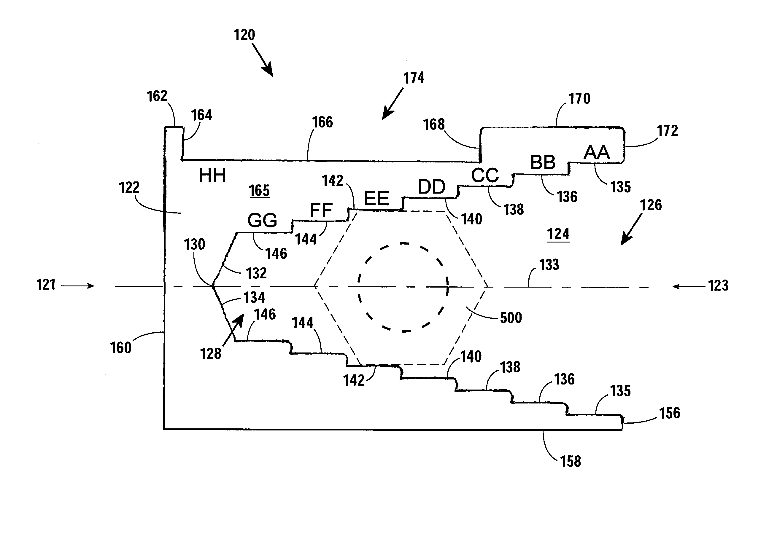
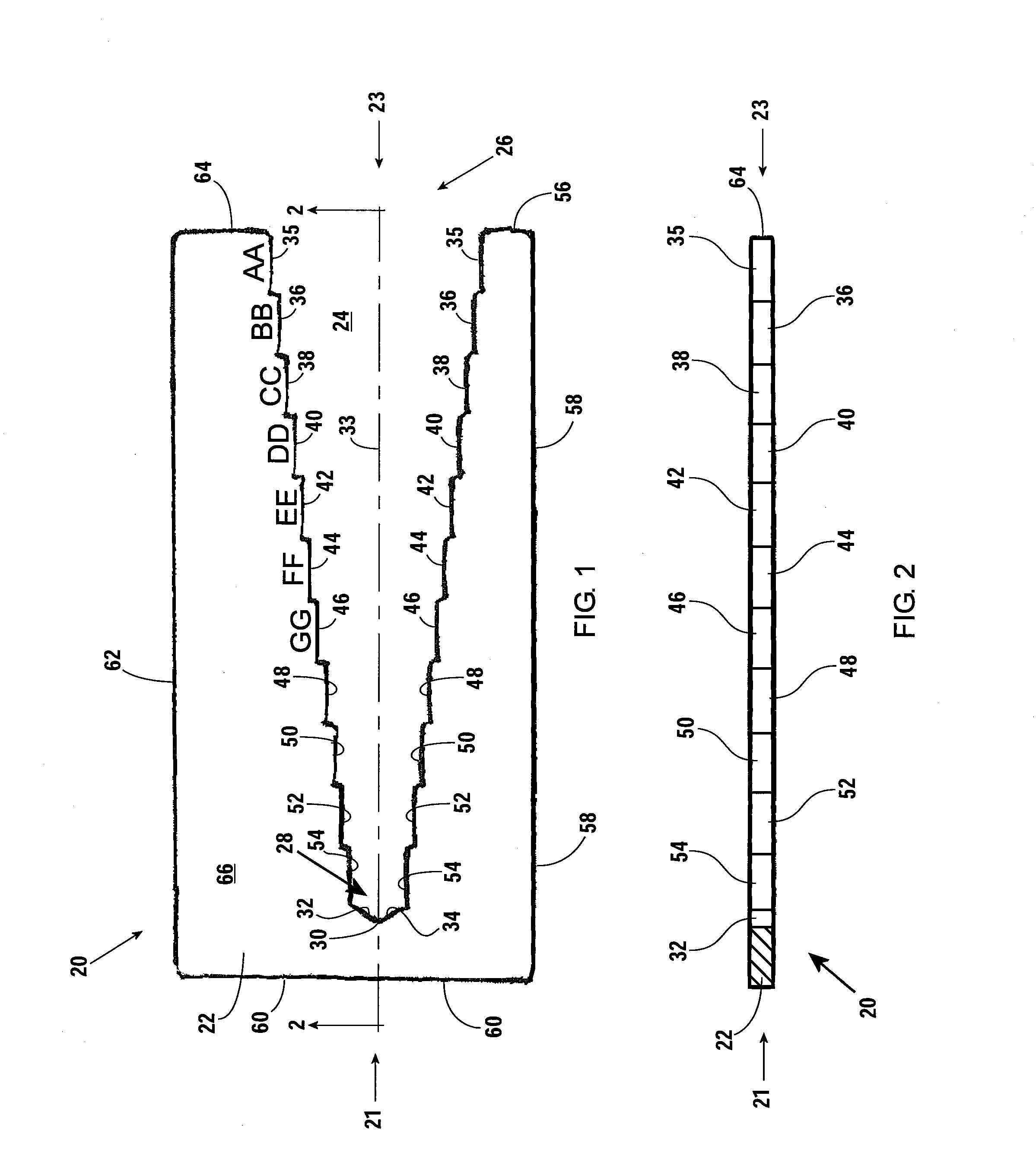
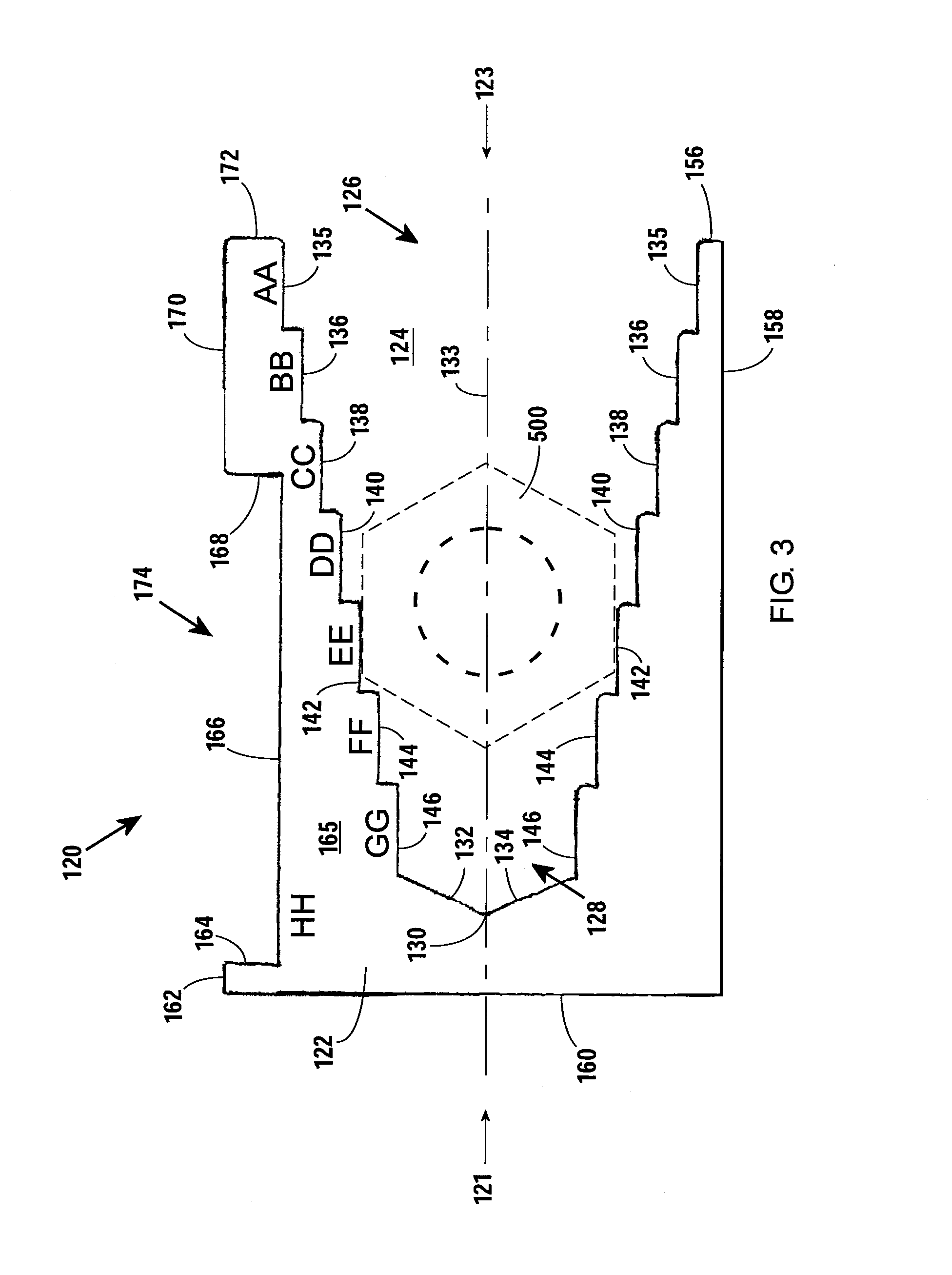
[0013]FIGS. 1-2 show a first embodiment 20 of the invention. The embodiment 20 is a generally “U”-shaped, metal body 22 having a first end 21 and a second end 23. The body 22 defines an interior cavity 24 having an open end 26 and a closed end 28. The cavity 24 is widest at the open end 26 and narrows toward the closed end 28, which is coterminal with a junction 30 of two rectangular walls 32, 34 angled 120-degrees apart. The cavity 24 is symmetrical about a longitudinal line 33 that intersects the junction 30 and extends between the first end 21 and second end 23.

[0014]The cavity 24 is partially defined by a plurality of parallel surfaces. The surfaces are arranged in opposing pairs, with both surfaces of each pair being identical in length. A first pair of surfaces 35 is adjacent to the open end 26 of the cavity 24 with the surfaces 35 spaced a first distance from one another. A second pair of surfaces 36 is longitudinally positioned between the first pair of surfaces 35 and the c...


PUM


Abstract

A measuring device for measuring nuts, bolt heads, washers and the like that includes a body having a first end, an opposing second end, and a longitudinal reference line extending between the first end and the second end; a first pair of parallel surfaces of equal length, the first pair of opposing parallel surfaces longitudinally between the first end and the second end, the surfaces of the first pair spaced apart by a first distance; a second pair of parallel surfaces of equal length, the second pair of parallel surfaces longitudinally between the first pair of parallel surfaces and the first end, the surfaces of the second pair spaced apart by a second distance that is smaller than the first distance; and a pair of nonparallel surfaces connected at an obtuse angle, the opposing nonparallel surfaces longitudinally between the second pair of opposing parallel surfaces and the first end.

Description

CROSS-REFERENCE TO RELATED APPLICATIONS[0001]This original non-provisional application claims the benefit of and priority to U.S. provisional application 61 / 939,496, filed Feb. 13, 2014, which is incorporated by reference.FEDERALLY-SPONSORED RESEARCH[0002]Not applicable.BACKGROUND OF THE INVENTION[0003]1. Field of the Invention[0004]This application relates to fasteners. More specifically, the application relates to a measuring device for nuts, bolt heads, washers and other small tools.[0005]2. Background of the Related Art[0006]In the mechanical arts, it is often necessary to quickly and accurately measure the size of nuts, bolt heads, or other fasteners (or fastening tools). Often, however, a measuring tool is not handy because it is bulky or because it is located elsewhere. This results in additional time (relative to having the tool on person) required for a technician or mechanic to size the fastener. In some cases, the technician might simply guess at the size, which could res...

Claims


Application Information

Patent Timeline
IPC IPC(8): G01B3/38
CPCG01B3/38G01B3/34
Inventor RODRIGUEZ, DAVID
Owner RODRIGUEZ DAVID
Learn More