Method for working steel sheet, and apparatus for working steel sheet

a technology for working steel sheets and steel sheets, applied in shearing apparatus, shearing machines, manufacturing tools, etc., can solve the problems of high equipment investment, increased size of pressing machines, and high cost of laser cutters, and achieve the effect of inexpensive work of steel sheets

Active Publication Date: 2015-10-01
TOYOTA JIDOSHA KK
View PDF6 Cites 7 Cited by
  • Summary
  • Abstract
  • Description
  • Claims
  • Application Information

AI Technical Summary

Benefits of technology

[0020]The present invention makes it possible to inexpensively work a steel sheet.

Problems solved by technology

However, the above-mentioned pressing machine needs an extremely large load for pressing because the plural pairs of dies works the plurality of steel sheets at the same time, which causes a problem of an increase in size of the pressing machine, for example.
However, adopting the laser cutter needs a high equipment investment because the laser cutter is expensive.
Therefore, the technique disclosed in JP-A 2000-79424 has a disadvantage of increase in cost required to trim the steel sheet with the laser cutter.

Method used


Image

  • Method for working steel sheet, and apparatus for working steel sheet
  • Method for working steel sheet, and apparatus for working steel sheet
  • Method for working steel sheet, and apparatus for working steel sheet

Examples


first embodiment

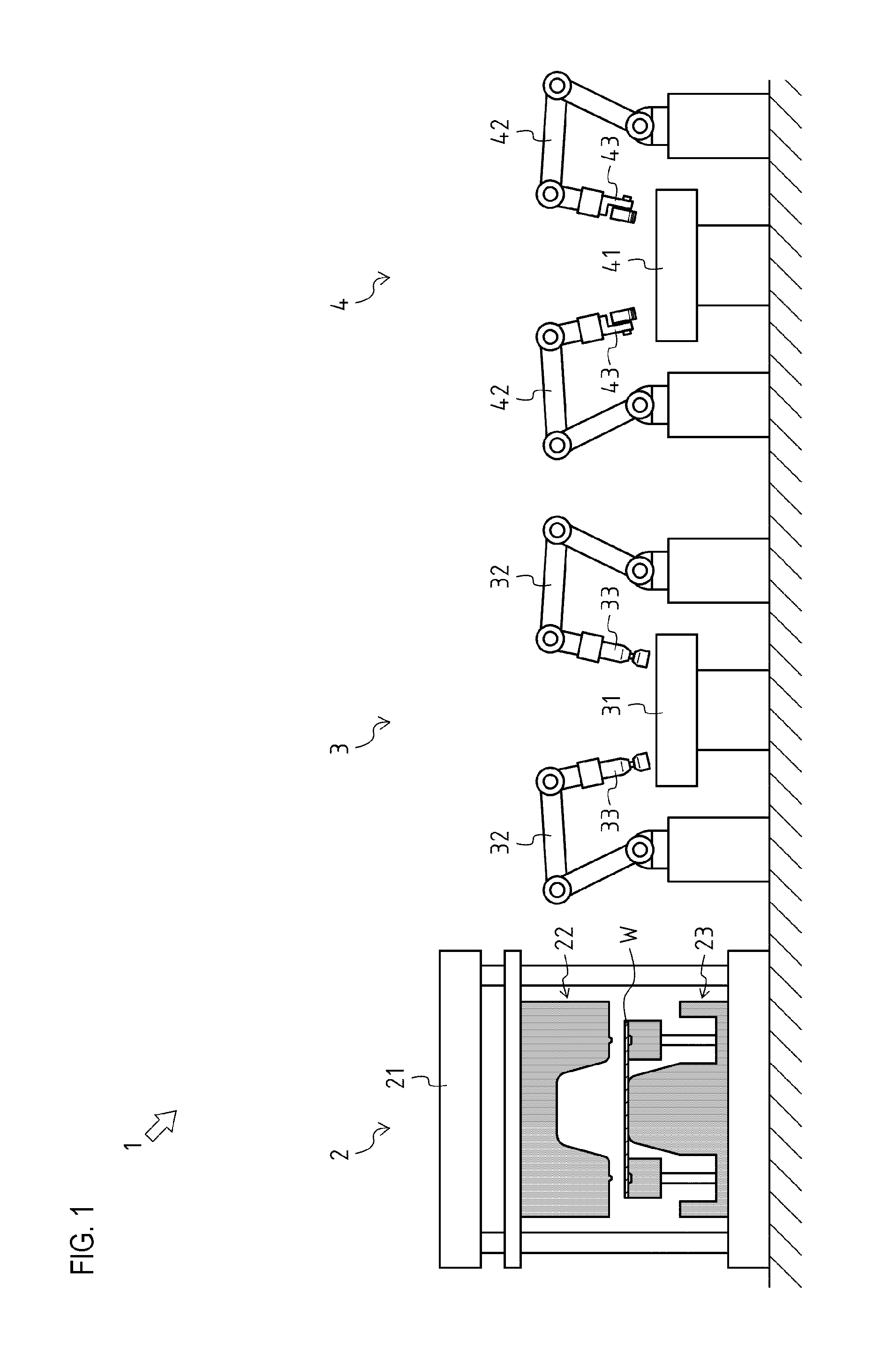
[0040]With reference to FIGS. 1 and 5, an apparatus 1 as a first embodiment of an apparatus for working a steel sheet according to the present invention is described below.

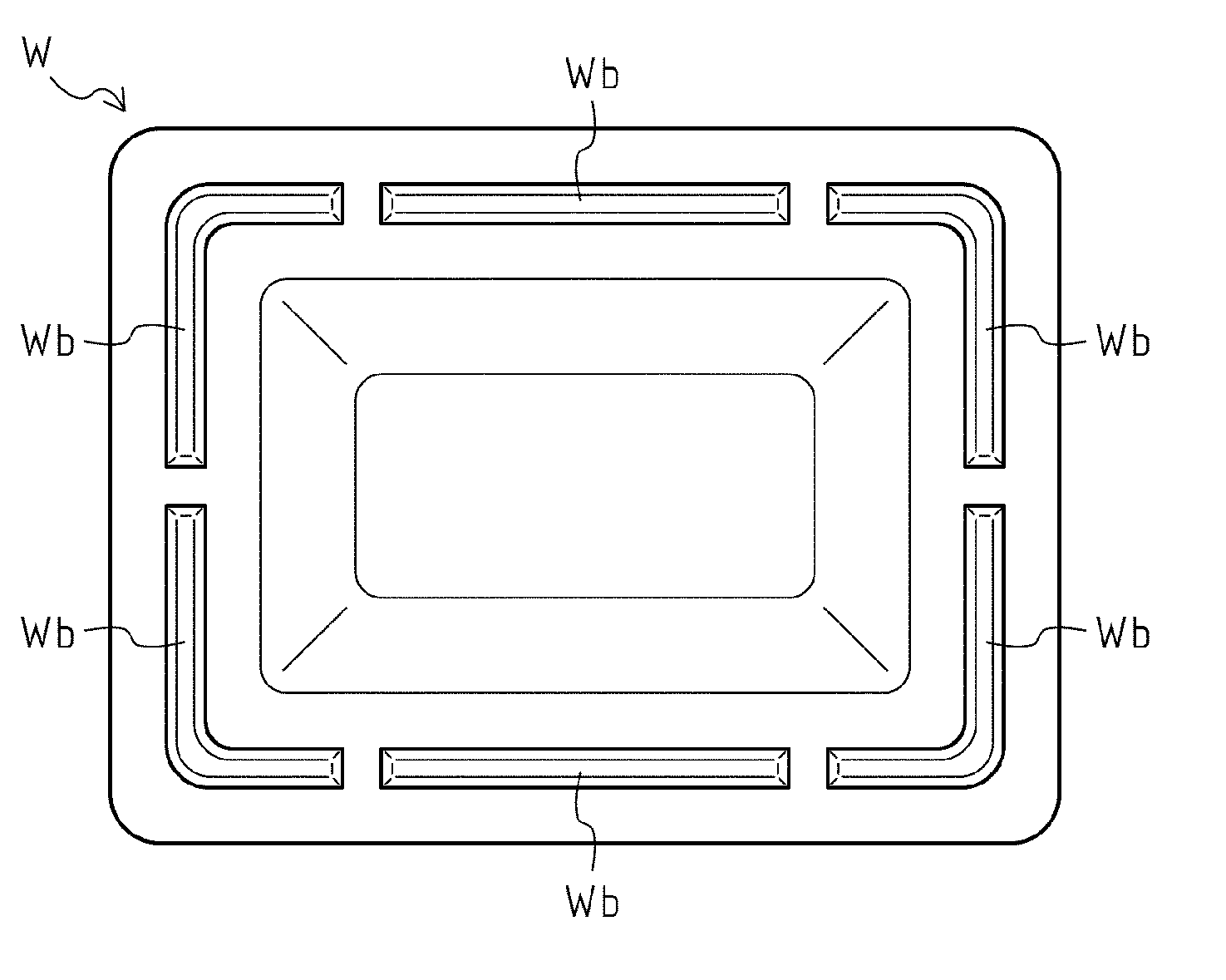
[0041]The apparatus 1 works a workpiece W which is a steel sheet into a predetermined shape.

[0042]For convenience, a top-bottom direction in FIG. 1 is defined as a top-bottom direction of the apparatus 1.

[0043]As shown in FIG. 1, the apparatus 1 includes a drawing device 2, a cutting device 3, and a bending device 4.

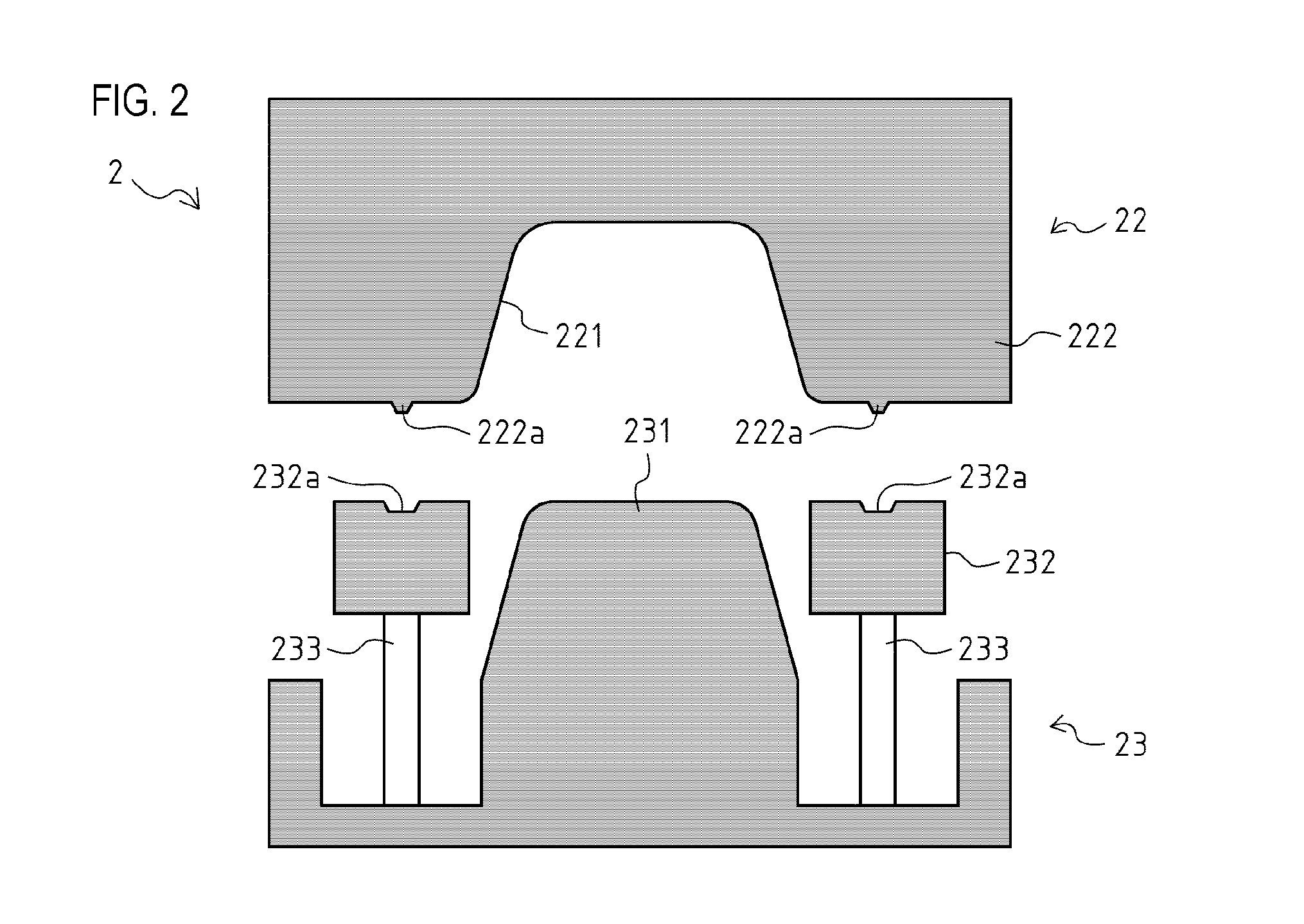
[0044]The drawing device 2 has a pressing machine 21, and upper and lower dies 22 and 23. The drawing device 2 is configured to draw the workpiece W.

[0045]The pressing machine 21 is configured so that the upper and lower dies 22 and 23 are attached thereto, and that the upper die 22 moves into and out of proximity with the lower die 23.

[0046]The upper and lower dies 22 and 23 constitute a pair of dies attached to the pressing machine 21, and are arranged above and below the pressing machine 21, respect...

second embodiment

[0142]With reference to FIGS. 14 and 16, an apparatus 1001 as a second embodiment of an apparatus for working a steel sheet according to the present invention is described below.

[0143]The apparatus 1001 works the workpiece W which is a steel sheet into a predetermined shape.

[0144]For convenience, a top-bottom direction in FIG. 14 is defined as a top-bottom direction of the apparatus 1001.

[0145]Hereinafter, common parts between the apparatus 1001 and the apparatus 1 are indicated by the same reference signs, and descriptions thereof are omitted.

[0146]As shown in FIG. 14, the apparatus 1001 includes a drawing device 1002, a cutting device 1003, and the bending device 4.

[0147]The drawing device 1002 has the pressing machine 21, and upper and lower dies 1022 and 1023. The drawing device 1002 is configured to draw the workpiece W.

[0148]In the present embodiment, the upper and lower dies 1022 and 1023 are attached to the pressing machine 21.

[0149]The upper and lower dies 1022 and 1023 con...


PUM

PropertyMeasurementUnit
circumferenceaaaaaaaaaa
heightaaaaaaaaaa
shapeaaaaaaaaaa

Abstract

Provided is a technique capable of inexpensively working a steel sheet. A method for working a workpiece with an apparatus for working a workpiece, includes: a drawing step for performing drawing with a drawing device having an upper die and a lower die; and a cutting step for cutting the drawn workpiece with a cutting device having nibblers. The nibbler has a cylindrical case, a punch housed in the case, which reciprocates in a top-bottom direction to punch the workpiece, and a die arranged below the case, the die having a die hole into which the punch enters, and an ejecting hole communicating with the die hole, through which a scrap is ejected. The nibbler trims the workpiece fed between the case and the die.

Description

TECHNICAL FIELD[0001]The present invention relates to a method and an apparatus for working a steel sheet into a predetermined shape.BACKGROUND ART[0002]Conventionally, when a steel sheet is worked, a pressing machine is used which is provided with plural pairs of dies having different uses.[0003]For example, JP Pat. No. 3685961 discloses a pressing machine provided with a pair of dies for trimming a drawn steel sheet, a pair of dies for roughly bending the trimmed steel sheet, and a pair of dies for finally bending the roughly bent steel sheet.[0004]The pressing machine can work a plurality of (three) steel sheets existing in different states at the same time.[0005]However, the above-mentioned pressing machine needs an extremely large load for pressing because the plural pairs of dies works the plurality of steel sheets at the same time, which causes a problem of an increase in size of the pressing machine, for example.[0006]JP-A 2000-79424 discloses a technique including drawing a...

Claims


Application Information

Patent Timeline
Patent Type & Authority Applications(United States)
IPC IPC(8): B21D24/16B23D27/00B21D22/22
CPCB21D24/16B23D27/00B21D22/22B21D35/001
Inventor SAITO, KAZUMI
Owner TOYOTA JIDOSHA KK
Why Eureka
Try Eureka