Electric tool

Active Publication Date: 2015-10-01
MAKITA CORP
View PDF13 Cites 20 Cited by
  • Summary
  • Abstract
  • Description
  • Claims
  • Application Information

AI Technical Summary

Benefits of technology

[0011]According to the above mentioned invention, the switch is not turned ON unless the switch operating portion is moved to the position where the switch can be operated. Further, the switch is prevented from being turned ON by the operating member with the switch arranged between the pivotal movement supportin

Problems solved by technology

However, in the case where the operating member is formed to be elongated along the housing, even though the loc

Method used


Image

  • Electric tool
  • Electric tool
  • Electric tool

Examples


Embodiment Construction

[0021]Embodiments of the invention will be described with reference to the drawings.

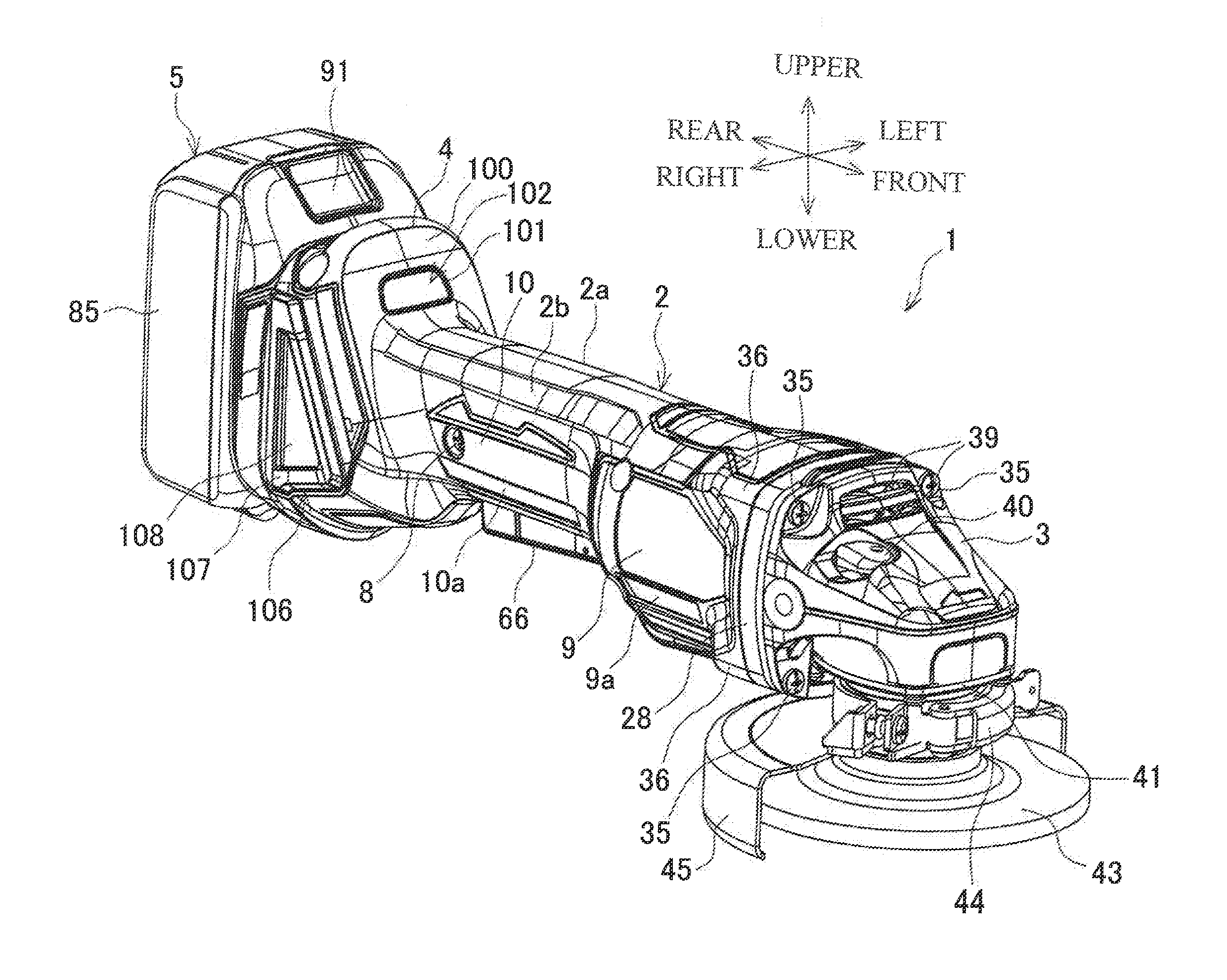
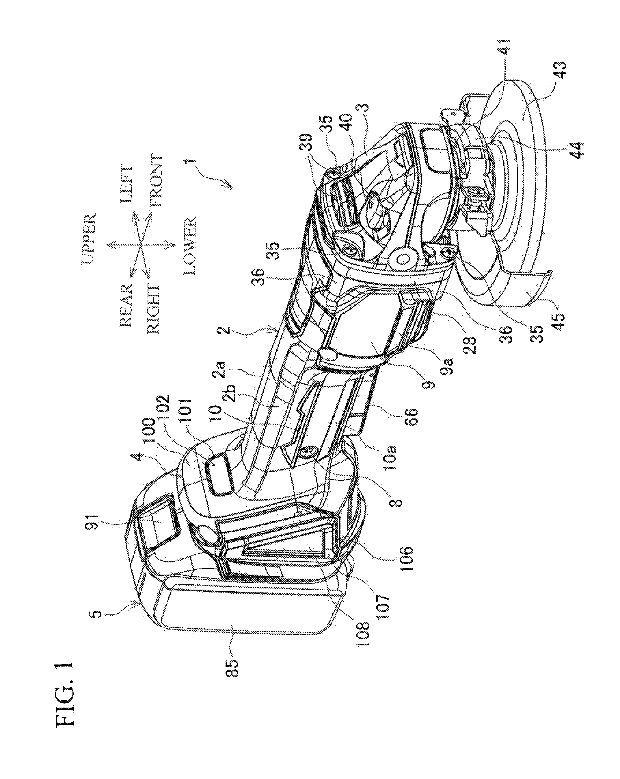
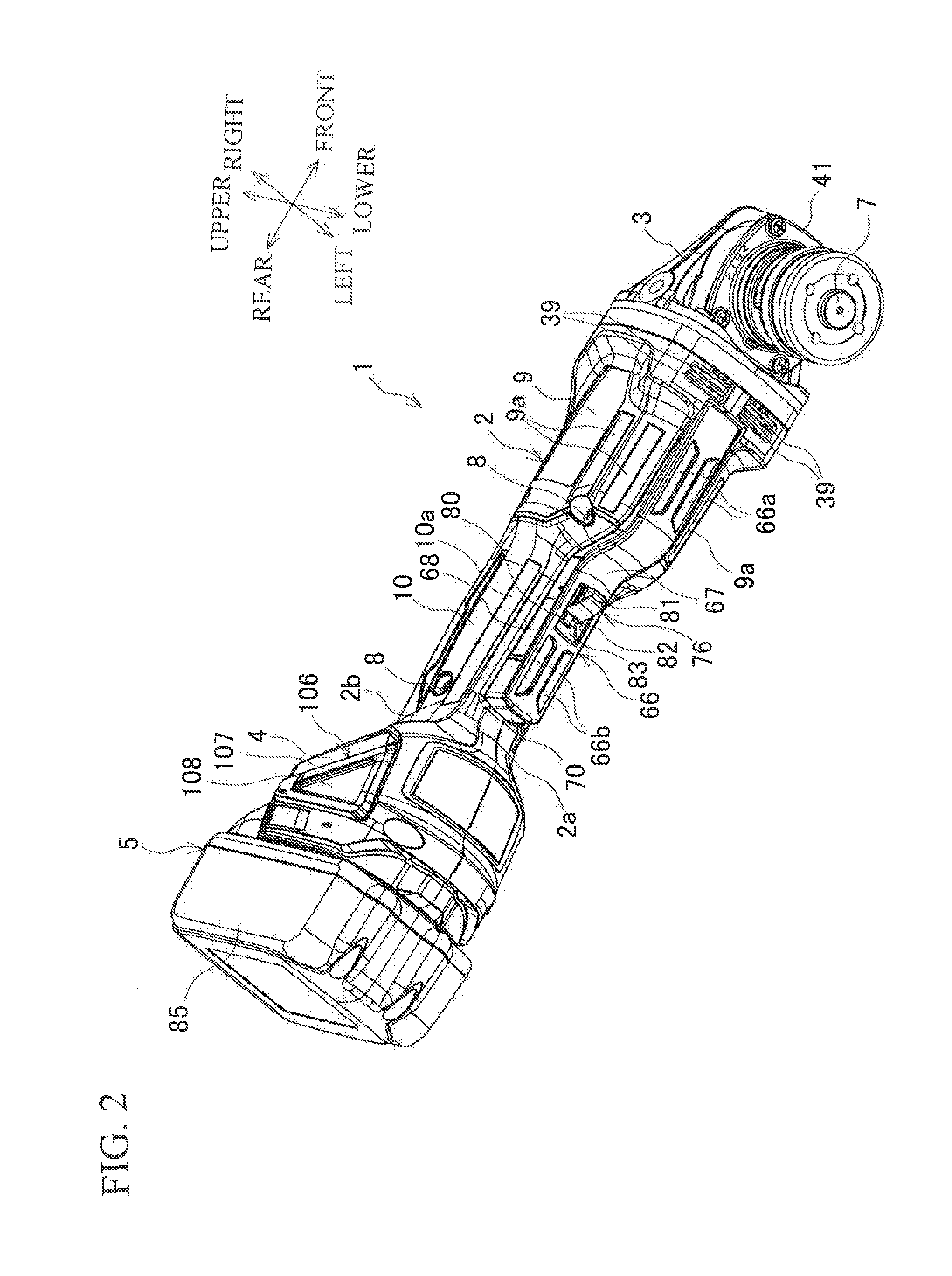
[0022]FIGS. 1 and 2 are perspective views of a rechargeable grinder as an example of an electric tool, and FIG. 3 is a vertical cross-sectional view of the rechargeable grinder. A rechargeable grinder (hereinafter referred to simply as a “grinder”) 1 includes a cylindrical main body housing 2, a brushless motor 6 accommodated in the main body housing 2, a gear housing 3 coupled to the front of the main body housing 2, a spindle 7 projecting downward from the gear housing 3, a battery mounting portion 4 formed at a rear end of the main body housing 2, and a battery pack 5 configured to serve as a power source mounted on the battery mounting portion 4. The main body housing 2 is formed by assembling a pair of left and right half housing 2a and 2b with screws 8 and 8, and a storage portion of the brushless motor 6 corresponds to a thickest cylindrical portion 9. A portion rearward of the cylindrical por...


PUM


Abstract

A rechargeable grinder includes a brushless motor, a main body housing configured to accommodate the brushless motor, a main switch and a micro switch configured to distribute power to the brushless motor, and a switch lever capable of moving with respect to the main switch and the micro switch, wherein a lock off lever capable of operating the micro switch in association with movement of the switch lever toward a switch is provided so as to be movable between a lock release position in which the micro switch can be operated and a lock position in which the micro switch cannot be operated.

Description

BACKGROUND OF THE INVENTION[0001]This application claims the benefit of Japanese Patent Application Number 2014-075559 filed on Apr. 1, 2014, the entirety of which is incorporated by reference.FIELD OF THE INVENTION[0002]The present invention relates to an electric tool such as a rechargeable grinder configured to be switched ON by an operation of an operating member.DESCRIPTION OF THE RELATED ART[0003]In an electric tool such as a rechargeable grinder or the like, a switch accommodated in a housing is turned ON by a push-in operation of an operating member such as a lever provided on the housing to drive a motor, as disclosed in JP 2013-22702-A. In this case, the operating member is provided with a lock-off member configured to prevent the operating member from being pushed in by coming into abutment with the housing and maintain the switch in an OFF state so as to avoid the operating member from being accidentally pushed in. When an operator uses the tool, the operating member is ...

Claims


Application Information

Patent Timeline
IPC IPC(8): H02K11/00H01H9/20H02K7/14
CPCH02K11/0063H02K7/14H01H2300/024H01H2231/048H01H9/20B24B23/02B25F3/00B25F5/00B24B41/00B24B47/12B25F5/02H02K11/28
Inventor MIZUTANI, AKIRAKAWAKAMI, TAKAHIROISHIKAWA, SHOICHI
Owner MAKITA CORP
Why Eureka
Try Eureka