

Ratchet type one-way clutch
a one-way clutch and ratchet technology, applied in the direction of clutches, mechanical actuated clutches, clutches, etc., can solve the problems of inability to impart urging force, inability to apply a stable urging force to the pawl member, and inability to apply urging for
- Summary
- Abstract
- Description
- Claims
- Application Information
AI Technical Summary
Benefits of technology
Problems solved by technology
Method used
Image

Examples
first embodiment
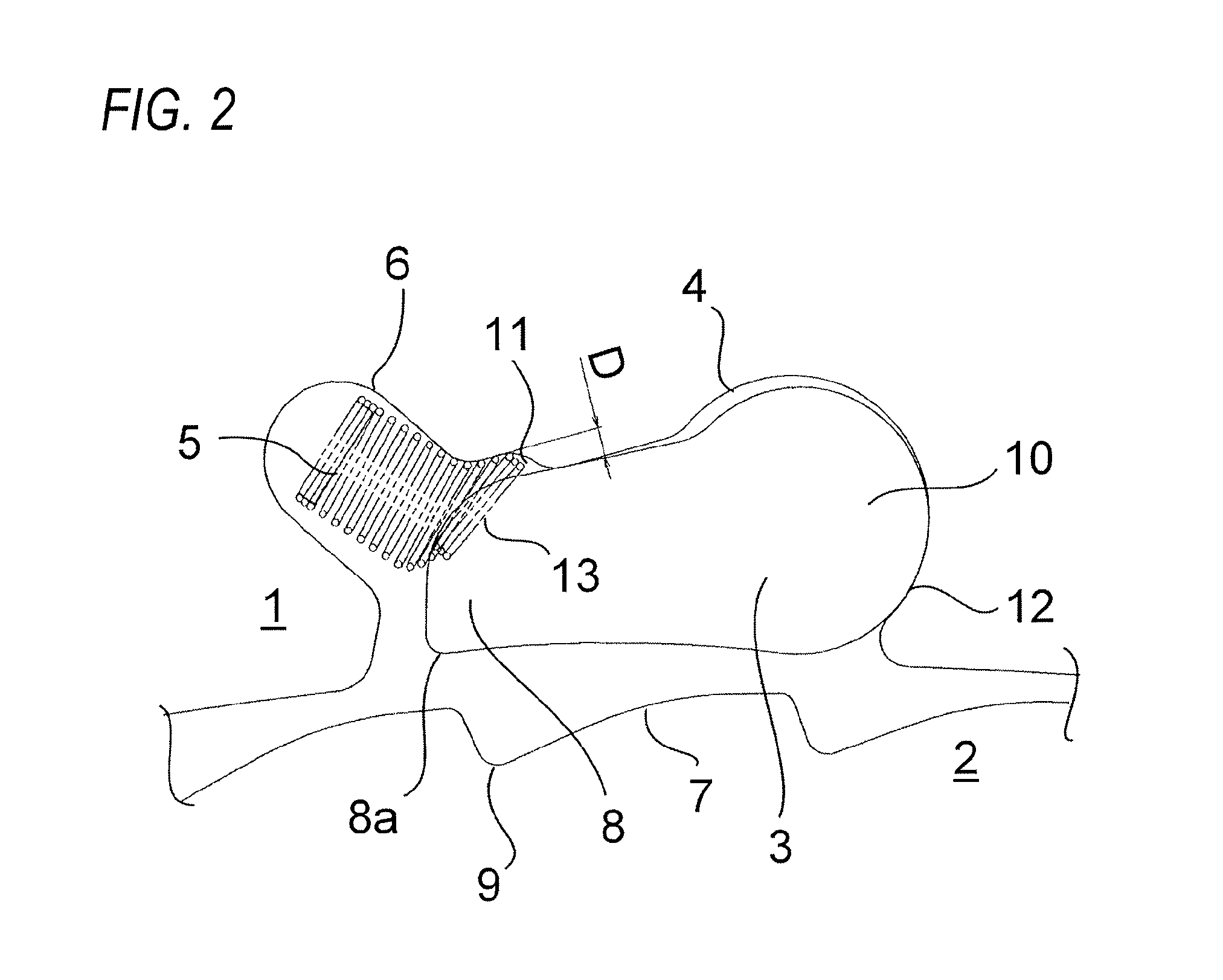
[0028]FIG. 2 is a schematic diagram of the first embodiment of the present invention showing a relationship among the spring, pawl member and outer race as enlargement. FIG. 3 is a schematic diagram showing a relationship among the conventional spring, pawl member and outer race for comparison with the first embodiment shown in FIG. 2.
[0029]When the ratchet type one-way clutch 30 is in operation or when it turns from the idle state to a reverse rotation and thus to the locked state, the pawl member 3, which engages with the notch 7, may be flicked and displaced from the position shown by a dashed line 21 to the position shown by a continuous line 22. Here, as illustrated in FIG. 3, the spring 5 abutting the pawl member 3 moves to the bending direction, which may cause the edge portion of the spring 5 to be deformed by being sandwiched at a slight gap 20 between the outer race 1 and the pawl member 3.
[0030]As a result of such deformation, the spring 5 has an unstable attitude during ...
second embodiment
[0035]FIG. 4 is a schematic diagram of the second embodiment of the present invention showing a relationship among the spring, pawl member and outer race as an enlargement.
[0036]In the second embodiment, the means for stabilizing the urging force of the spring is a guide member 15 provided at an axial end of the spring 5. The guide member 15 is arranged at an axial end 14 of the spring 5 on a bottom part 16 side of the spring pocket 6 in which the spring 5 is housed.
[0037]The guide member 15 includes a rectangular or polygonal plate 17 having a slightly larger size than the outer diameter of the spring 5 and a cylindrical portion 18, and is fixed to the spring 5 by inserting cylindrical portion 18 into the inner diameter of the spring 5. The spring 5 is guided by the guide member 15 along the inner wall of the spring pocket 6.
[0038]A conventional spring, with which no guide member is provided, is supported at two points on a circumference of the spring 5 that are opposed by 180 degr...
third embodiment
[0041]FIG. 5 is a schematic diagram of the third embodiment of the present invention showing a relationship among the spring, pawl member and outer race as enlargement. The third embodiment is a combination of the first and second embodiments. As the guide member 15 of this embodiment, the one that is same as the guide member 15 described with reference to FIG. 4 may be used.
[0042]When the ratchet type one-way clutch 30 is in operation, the spring 5 applies a stable urging force to the pawl member 3 while maintaining a stable attitude due to the guide member 15 as shown in FIG. 4. However, when the pawl member 3 is engaged with the notch 7 and then flicked, the space 11 makes it possible for the end turn of the spring 5 to escape into the space 11 as shown in FIG. 5. This allows the spring 5 to be prevented from deformation.
PUM
 Abstract
Description
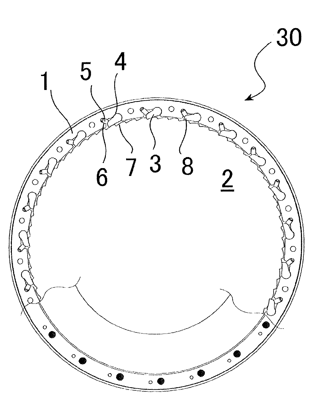
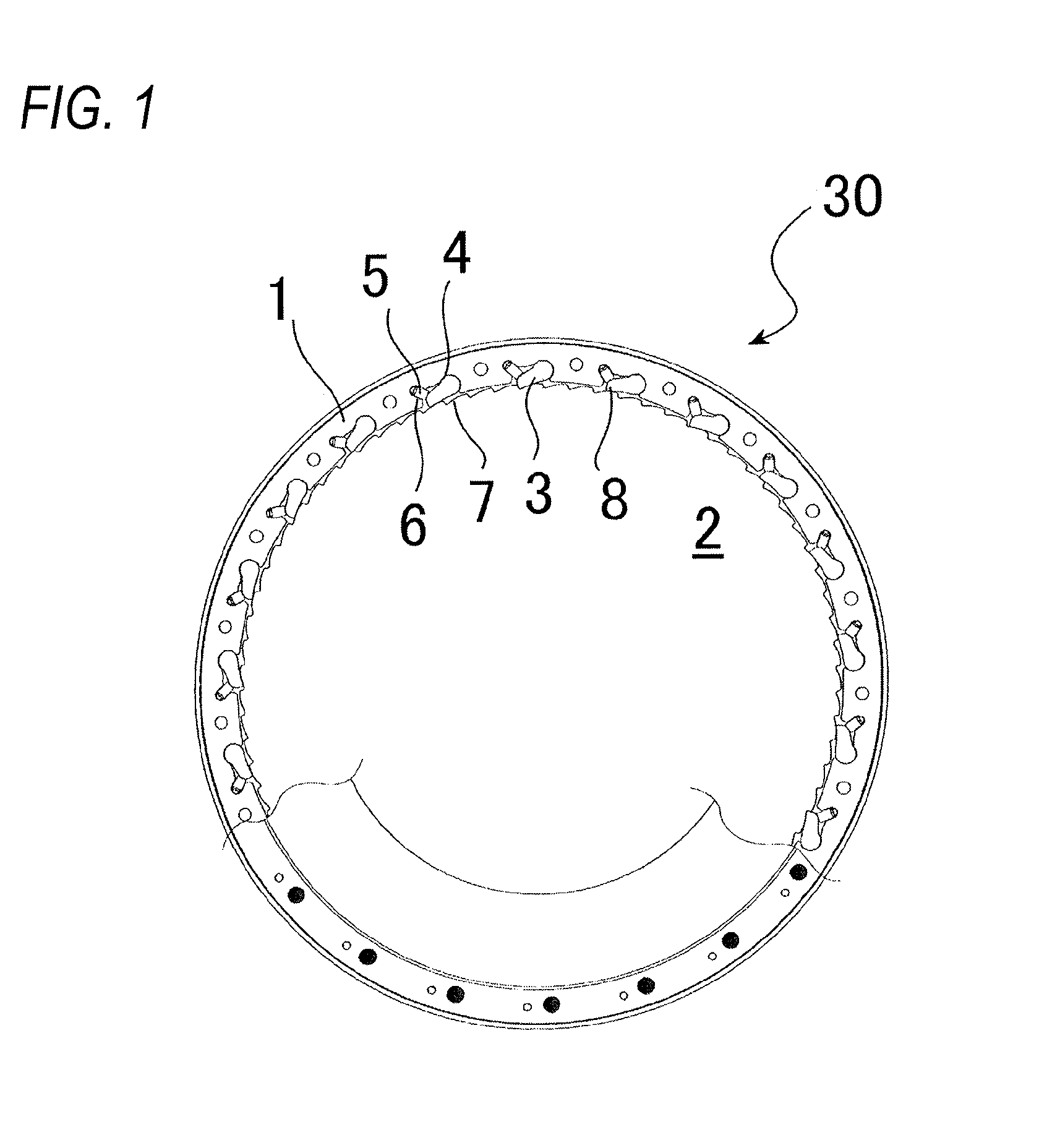
Claims
Application Information