Transmitter for an inductive power transfer

Inactive Publication Date: 2015-10-15
APPLE INC
View PDF6 Cites 29 Cited by
  • Summary
  • Abstract
  • Description
  • Claims
  • Application Information

AI Technical Summary

Benefits of technology

[0008]According to one exemplary embodiment there is provided an inductive power transfer transmitter including: an enclosure for accommodating devices to be energised having one or more side walls; one or more coils fo

Problems solved by technology

However, requiring precise alignment undermines one of the key objectives of some IPT systems, which is uncomplicated charging and powering of devices, with minimal user participation.
However, the magnetic field produced by such a configuration is not uniform, and can be particularly weaker towards the centre of the coil.
However, the same disadvan

Method used


Image

  • Transmitter for an inductive power transfer
  • Transmitter for an inductive power transfer
  • Transmitter for an inductive power transfer

Examples


Embodiment Construction

[0023]Coil Arrangement

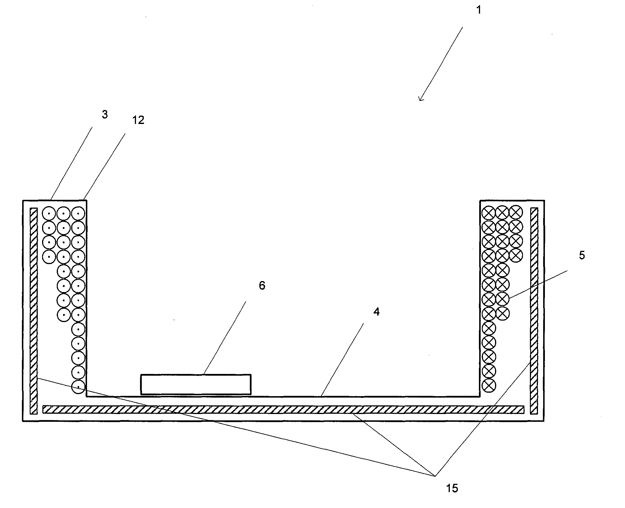
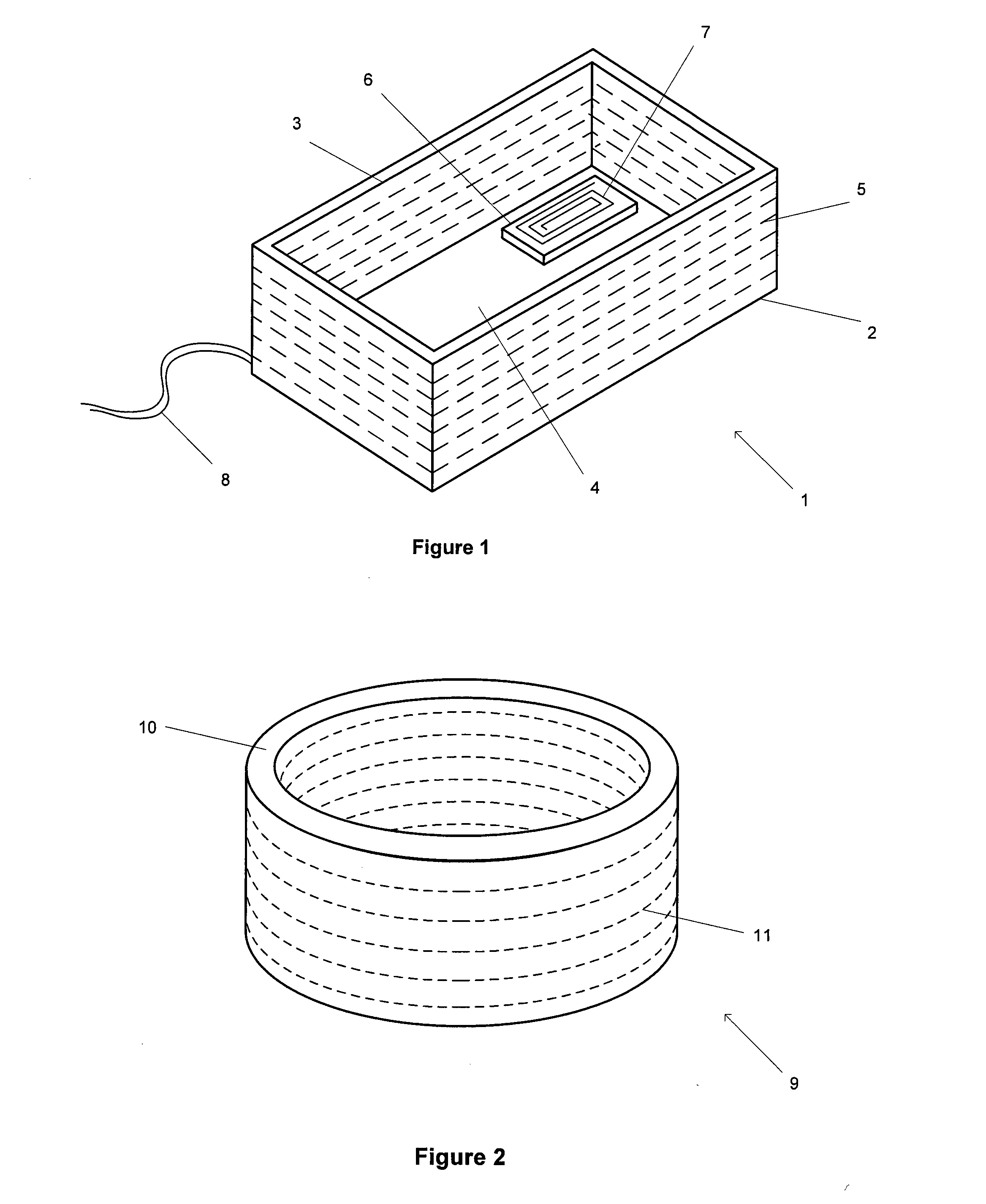
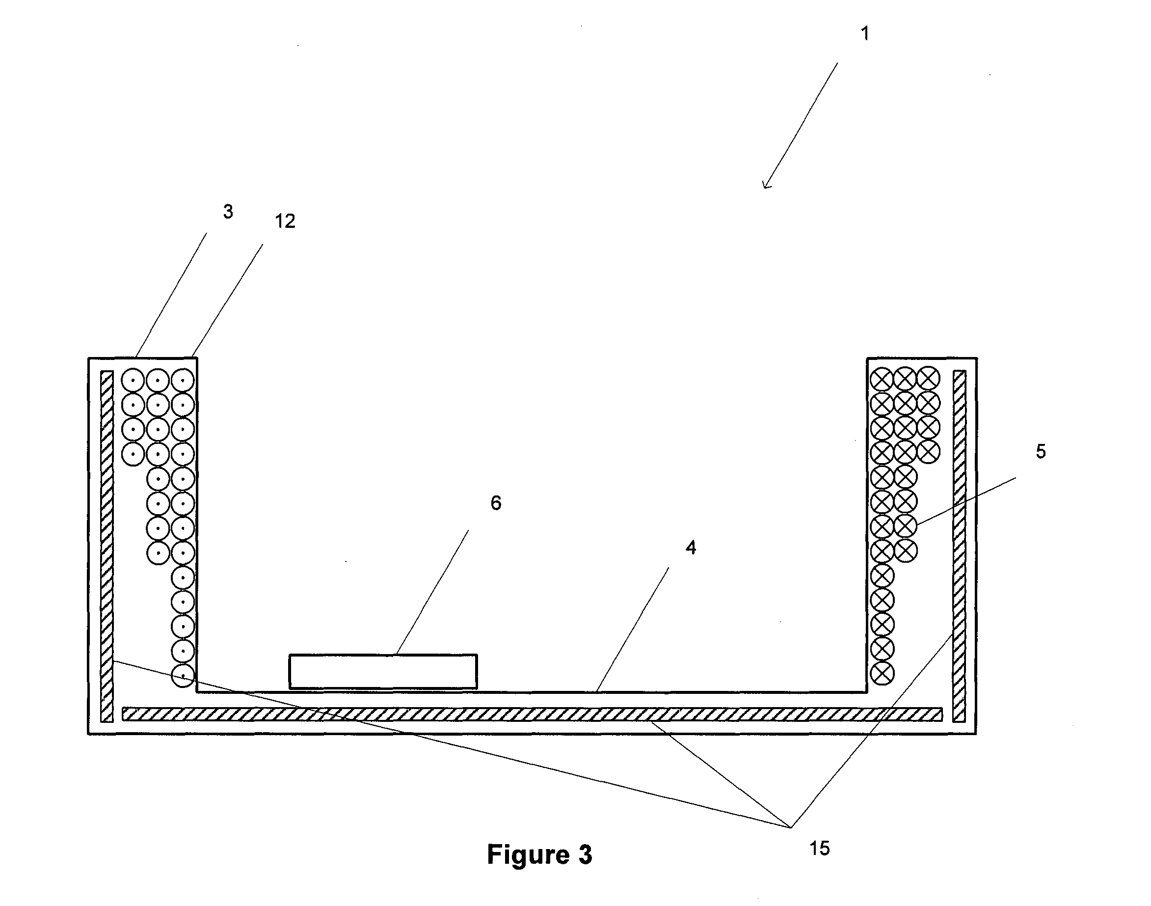
[0024]Referring to FIG. 1, there is shown a transmitter 1 for an IPT system according to an embodiment of the present invention. The transmitter takes the form of a charging enclosure 2 with sidewalls 3 and a base portion 4. The transmitter includes a coil 5 that generates a time-varying magnetic field inside the enclosure. A device 6, placed inside the enclosure, includes a receiver coil 7, which inductively couples with the time-varying magnetic field and produces a current that can be used to charge or power the device. The coil is contained with the sidewalls of the enclosure, and is wound about the perimeter of the enclosure, coplanar with the base portion, as shown by the dashed lines in FIG. 1.

[0025]The transmitter 1 is connected to a suitable power supply 8, and drive circuitry (not shown) is configured to drive the coil so that it generates the magnetic field. The drive circuitry is configured such that the coil 5 generates a time-varying magnetic fiel...


PUM


Abstract

An inductive power transfer transmitter that includes an enclosure for accommodating devices to be energised. The enclosure has one or more side walls and one or more coils for generating an alternating magnetic field within the enclosure. The density of the one or more coils varies with distance from an end of the one or more sidewalls. There is also disclosed an inductive power transmitter that includes one or more magnetically permeable layers wherein the combined thickness or the permeability of the one or more magnetically permeable layers varies.

Description

FIELD OF THE INVENTION[0001]The present invention is in the field of an inductive power transfer (IPT) system. More particularly, the invention relates to a power transmitter—having a novel configuration—for use in such systems.BACKGROUND OF THE INVENTION[0002]IPT systems are a well known area of established technology (for example, wireless charging of electric toothbrushes) and developing technology (for example, wireless charging of handheld devices on a ‘charging mat’). Typically, a primary side generates a time-varying magnetic field from a transmitting coil or coils. This magnetic field induces an alternating current in a suitable receiving coil that can then be used to charge a battery, or power a device or other load. In some instances, it is possible for the transmitter or the receiver coils to be connected with capacitors to create a resonant circuit, which can increase power throughput and efficiency at the corresponding resonant frequency.[0003]A basic problem that must ...

Claims


Application Information

Patent Timeline
IPC IPC(8): H02J5/00
CPCH02J5/005H02J7/025H02J50/10H01F27/02H01F27/24H01F38/14H01F27/324H02J7/0044H02J50/402
Inventor LI, HAO
Owner APPLE INC
Why Eureka
Try Eureka