Transmitter for an Inductive Power Transfer System

a technology of inductive power transfer and transmitter, which is applied in the direction of transformer/inductance magnetic cores, inductances, circuit arrangements, etc., can solve the problems of user participation, uncomplicated charging and powering of devices, and requiring precise alignment to undermine on

Inactive Publication Date: 2020-05-14
APPLE INC
View PDF0 Cites 0 Cited by
  • Summary
  • Abstract
  • Description
  • Claims
  • Application Information

AI Technical Summary

Benefits of technology

[0032]The benefit of the present invention can be seen in FIGS. 4a and 4b, which show a vertical cross-section of a transmitter 1 according to en embodiment of the present invention. FIGS. 4a and 4b illustrate a comparison between the magnetic fields produced by a coil arrangement with uniform density and a coil arrangement according to the present invention respectively. It will be observed that for the former scenario in FIG. 4a, the magnetic flux is concentrated towards the walls of the enclosure 13, with there being a region of lower magnetic flux towards the centre 14. Hence, to ensure sufficient power transfer to receivers that are placed in this central region, the power flow through the transmitter must be increased. This results in inefficient use of supply power. Further, receivers that are placed closer to the enclosure side walls are subjected to a stronger magnetic field than those placed at the centre. This requires receivers to regulate their power flow dependent on their precise location within the enclosure. It also increases parasitic heating in the device. FIG. 4b demonstrates the magnetic field according to the coil arrangement of the present invention. As will be observed, the variable coil density results in a more uniform magnetic field across the enclosure. Effectively, the additional windings make the magnetic field extend further into the enclosure. This helps resolve the issues arising from the non-uniform field described above. In particular, the power flow through the transmitter can be decreased whilst still ensuring sufficient power transfer to the receiver, regardless of its placement inside the enclosure. Having decreased power flow in the transmitter minimises inefficiencies and lessens parasitic heating. Those skilled in the art will understand that the field shown in FIG. 4b is qualitative in order to demonstrate the principle of the invention. In practice, the precise coil arrangement that is required to achieve the desired field characteristics is dependent on many variables, such as dimensions and the power rating. It will be appreciated that the design of the coil arrangement will need to be adjusted to suit the particular application.

Problems solved by technology

However, requiring precise alignment undermines one of the key objectives of some IPT systems, which is uncomplicated charging and powering of devices, with minimal user participation.
However, the magnetic field produced by such a configuration is not uniform, and can be particularly weaker towards the centre of the coil.
However, the same disadvantages as with a charging pad can arise.
That is, the field is not uniform throughout the volume, being particularly weaker towards the centre.
Thus, to ensure sufficient power transfer even when a device is placed in the centre of the enclosure, the power on the primary side must be higher, which results in increased losses and decreased efficiency.

Method used


Image

  • Transmitter for an Inductive Power Transfer System
  • Transmitter for an Inductive Power Transfer System
  • Transmitter for an Inductive Power Transfer System

Examples


Embodiment Construction

[0023]Coil Arrangement

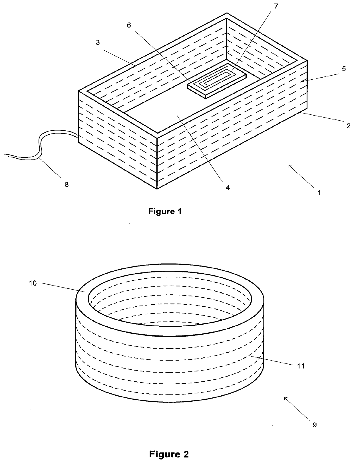
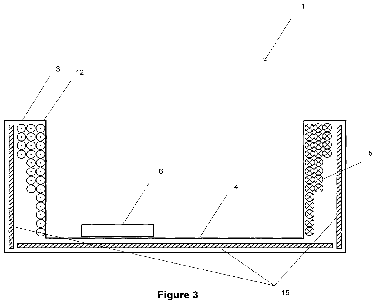
[0024]Referring to FIG. 1, there is shown a transmitter 1 for an IPT system according to an embodiment of the present invention. The transmitter takes the form of a charging enclosure 2 with sidewalls 3 and a base portion 4. The transmitter includes a coil 5 that generates a time-varying magnetic field inside the enclosure. A device 6, placed inside the enclosure, includes a receiver coil 7, which inductively couples with the time-varying magnetic field and produces a current that can be used to charge or power the device. The coil is contained with the sidewalls of the enclosure, and is wound about the perimeter of the enclosure, coplanar with the base portion, as shown by the dashed lines in FIG. 1.

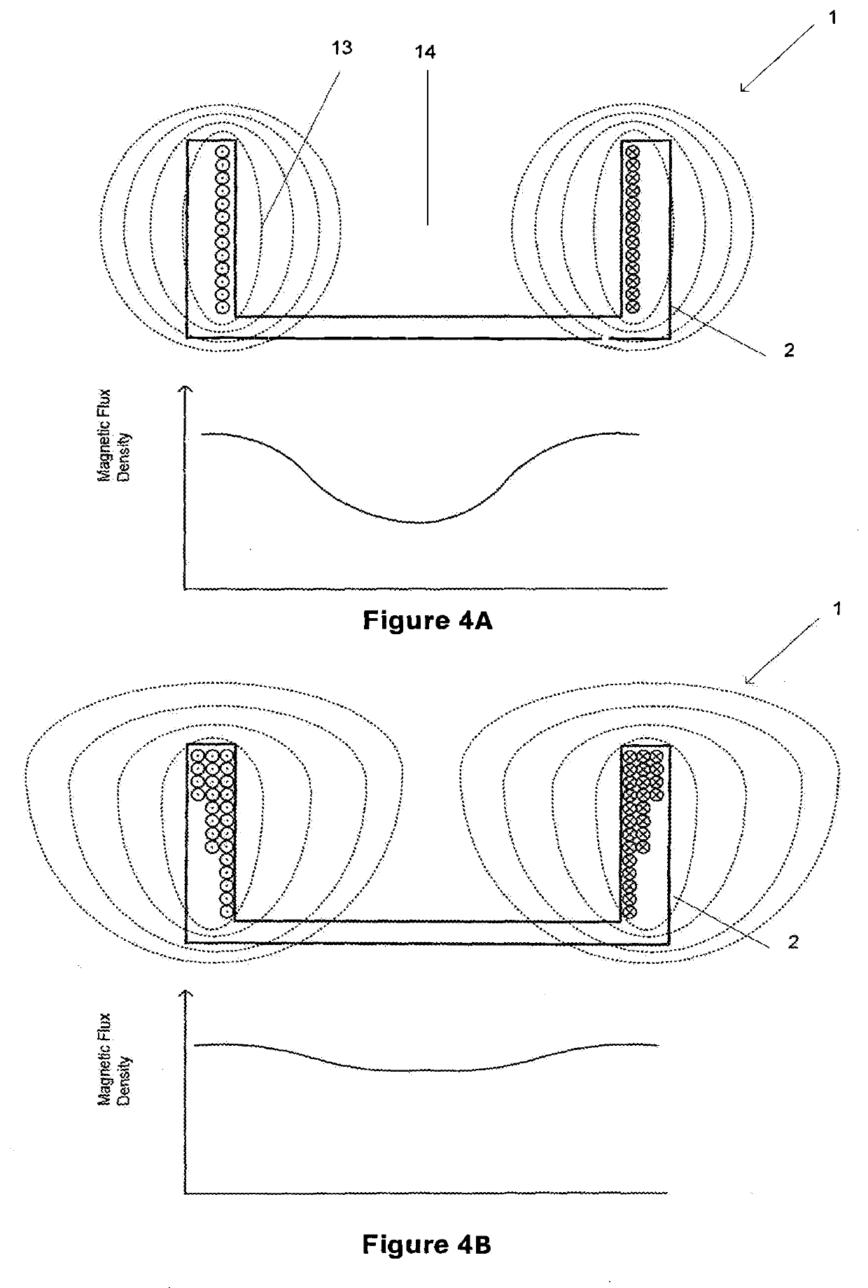
[0025]The transmitter 1 is connected to a suitable power supply 8, and drive circuitry (not shown) is configured to drive the coil so that it generates the magnetic field. The drive circuitry is configured such that the coil 5 generates a time-varying magnetic fiel...


PUM

PropertyMeasurementUnit
magnetic fieldaaaaaaaaaa
thicknessaaaaaaaaaa
heightaaaaaaaaaa

Abstract

An inductive power transfer transmitter that includes an enclosure for accommodating devices to be energised. The enclosure has one or more side walls and one or more coils for generating an alternating magnetic field within the enclosure. The density of the one or more coils varies with distance from an end of the one or more sidewalls.There is also disclosed an inductive power transmitter that includes one or more magnetically permeable layers wherein the combined thickness or the permeability of the one or more magnetically permeable layers varies.

Description

FIELD OF THE INVENTION[0001]The present invention is in the field of an inductive power transfer (IPT) system. More particularly, the invention relates to a power transmitter—having a novel configuration—for use in such systems.BACKGROUND OF THE INVENTION[0002]IPT systems are a well known area of established technology (for example, wireless charging of electric toothbrushes) and developing technology (for example, wireless charging of handheld devices on a ‘charging mat’). Typically, a primary side generates a time-varying magnetic field from a transmitting coil or coils. This magnetic field induces an alternating current in a suitable receiving coil that can then be used to charge a battery, or power a device or other load. In some instances, it is possible for the transmitter or the receiver coils to be connected with capacitors to create a resonant circuit, which can increase power throughput and efficiency at the corresponding resonant frequency.[0003]A basic problem that must ...

Claims


Application Information

Patent Timeline
Patent Type & Authority Applications(United States)
IPC IPC(8): H02J50/10H01F38/14
CPCH01F27/324H01F38/14H02J50/10H02J5/005H02J7/025H01F27/02H01F27/24H02J7/0044H02J50/402
Inventor LI, HAO
Owner APPLE INC
Why Eureka
Try Eureka