Chuck

a technology of chuck and chuck body, which is applied in the field of chuck, can solve the problems of inability to change the position of the clamping jaw during the machining process, loss of the central position of the clamped workpiece, and inherent weight of the workpiece, etc., and achieves the effect of precise centring of the workpiece, sufficient energy transfer and sufficient energy

Active Publication Date: 2020-12-29
SMW AUTOBLOK SPANNSYST GMBH
View PDF14 Cites 0 Cited by
  • Summary
  • Abstract
  • Description
  • Claims
  • Application Information

AI Technical Summary

Benefits of technology

[0010]To move the clamping jaws while the workpiece is clamped, i.e. while it is in the machining process, it is merely necessary to align the chuck body in such a way that the three charging stations provided inside the chuck body are flush with the coupling stations of the induction device, so that the prevailing inductance ensures a sufficient energy transfer to the particular electric motors. This energy transfer enables the control device to move the electric motors in two different directions of rotation with the effect that the particular clamping jaw can be moved either in the direction of the longitudinal axis of the chuck body or in the opposite direction. This means the positions of the clamping jaws can be individually adjusted, thereby achieving precise centring of the workpiece that is to be clamped and held.
[0011]While the chuck is stationary, for example for changing workpieces, the electric cables of the electric motor can be connected to a normal power source by means of a plug-and-socket connection, with the effect that sufficient energy is available for advancing and centring the workpieces when the chuck is at a standstill. The lower amount of electrical energy transferred via the induction device is however sufficient for driving the electric motors in such a way that the clamping jaws are slightly adjusted.

Problems solved by technology

It is not possible to change the position of the clamping jaws during the machining process.
The machining process often reduces the inherent weight of the workpiece to such an extent that the central position of the clamped workpiece is lost.
Such centring procedures extend the machining process, thus significantly increasing the operating costs to manufacture workpieces of this kind.

Method used


Image

  • Chuck
  • Chuck
  • Chuck

Examples


Embodiment Construction

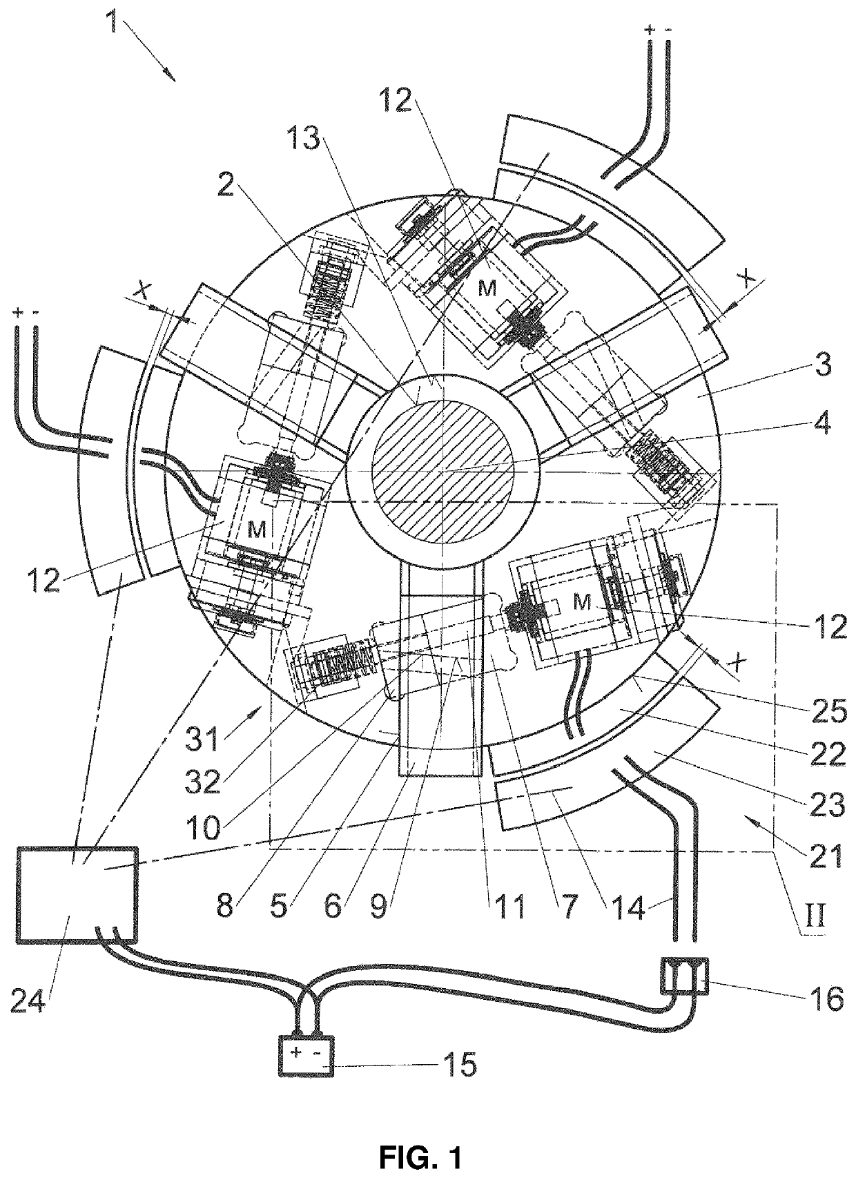
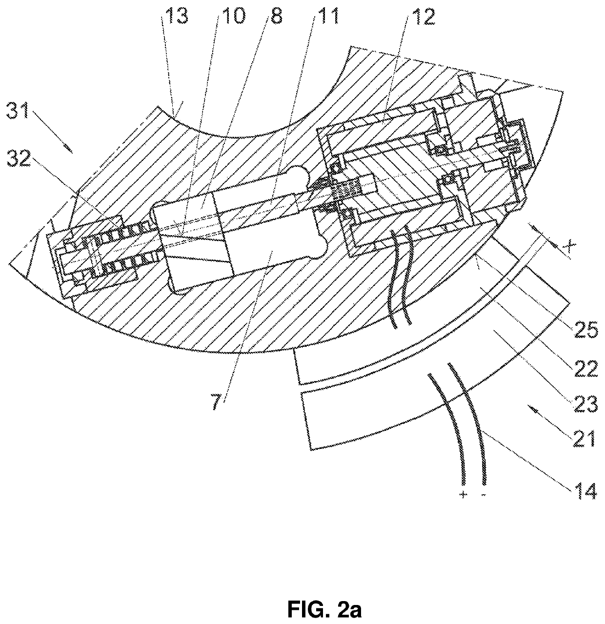
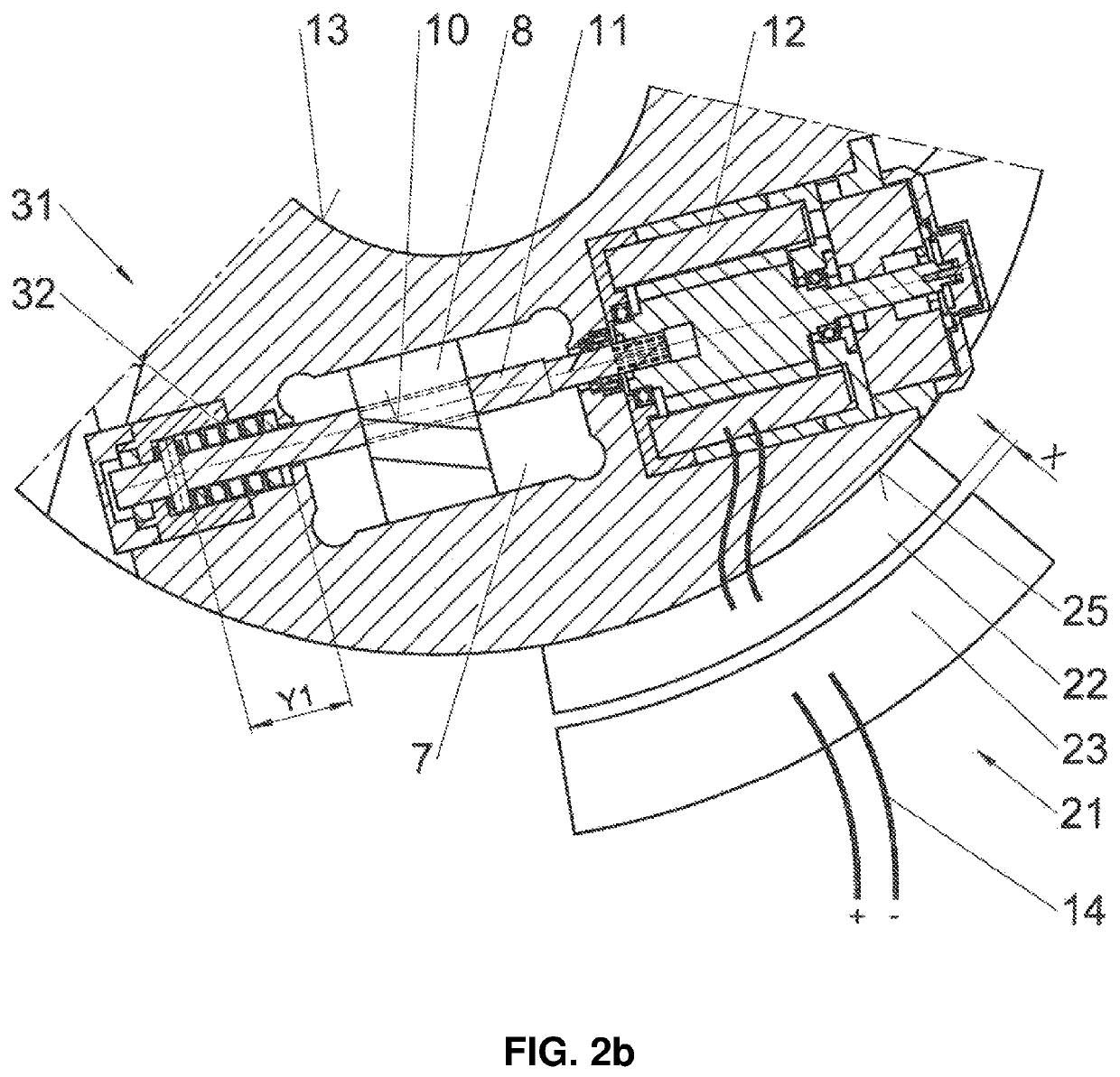
[0017]FIGS. 1, 2a, 2b and 2c disclose a chuck 1 which has the function of holding rotationally symmetrical workpieces 2 in the space on a machine tool that is not illustrated. The chuck 1 consists of a rotationally symmetrical chuck body 3, the longitudinal axis of which is provided with the reference number 4. For machining the workpiece 2, it is necessary for it to be positioned or aligned precisely in alignment with the longitudinal axis 4 of the chuck body 3. If the longitudinal axis of the workpiece 2 does not run flush with the longitudinal axis 4 of the chuck body 3, this will result in manufacturing errors during the machining process. Consequently, the chuck 1 according to the present invention should not only allow the flush alignment of the workpiece 2 with the longitudinal axis 4 of the chuck body 3 to be adjustable in the shortest possible time and with the least complicated design, but also the chuck 1 should allow the workpiece 2 be moved in its position or readjusted...


PUM

PropertyMeasurementUnit
forceaaaaaaaaaa
clamping forceaaaaaaaaaa
weightaaaaaaaaaa

Abstract

A chuck for supporting rotationally symmetrical workpieces to be machined, comprising a chuck body having at least three guideways worked into its end face running in the direction of the longitudinal axis of the chuck, at least three clamping jaws inserted individually into each of the guideways in a movable arrangement, and a driving means in a driving connection with the clamping jaws directly or via intermediate elements, with each of the clamping jaws of the chuck being adjustable during machining using driving means configured as an electric motor, with each clamping jaw having an electric motor arranged inside the chuck body, and when the chuck is stationary, the electric motors are electrically connected to a power source by means of a plug-and-socket connection and electrical cables, and / or when the chuck is rotating or at a standstill each electric motor is connected to the power source via an induction device.

Description

REFERENCE TO PENDING PRIOR PATENT APPLICATIONS[0001]This patent application claims benefit of European Patent Application No. 14 196 366.0, filed Dec. 4, 2014 and European Patent Application No. 15 171 103.3, filed Jun. 9, 2015, which patent applications are hereby incorporated herein by reference.FIELD OF THE INVENTION[0002]The present invention relates to a chuck for supporting rotationally symmetrical workpieces in accordance with the pre-characterising clause of Patent claim 1.BACKGROUND OF THE INVENTION[0003]Chucks of this kind have been disclosed in a wide range of different designs, for example in EP 2676756 A1. These chucks are chiefly used for holding a rotationally symmetrical workpiece centrally in space in relation to a longitudinal axis of a machine tool, so that it can machine with the greatest possible accuracy, maintaining machining tolerance errors as small as possible. At least three clamping jaws are to be provided in order to support the workpieces, and are mount...

Claims


Application Information

Patent Timeline
Patent Type & Authority Patents(United States)
IPC IPC(8): B23B31/16H02J5/00B23Q1/00B23B31/28B23B31/10B23Q1/52B23Q3/06
CPCB23B31/16045H02J50/10B23B31/101B23B31/28B23Q3/06B23Q1/522B23Q1/0009B23B2260/062B23B2270/022
Inventor MAURER, ECKHARD
Owner SMW AUTOBLOK SPANNSYST GMBH
Why Eureka
Try Eureka