Dynamic mixer, automatic mixing unit and method of installing and driving a dynamic mixer

a technology of automatic mixing and mixer, which is applied in the direction of mechanical equipment, couplings, transportation and packaging, etc., can solve the problems of not obtaining the desired final properties, the hexagonal shape of the generally plastic coupling socket cannot align correctly, and the rotor is not driven correctly, so as to achieve the effect of simple manufacturing

Active Publication Date: 2020-08-13
MEDMIX SWITZERLAND AG
View PDF1 Cites 0 Cited by
  • Summary
  • Abstract
  • Description
  • Claims
  • Application Information

AI Technical Summary

Benefits of technology

[0008]An exemplary prior art dynamic mixer is disclosed in WO2011 / 031440 A1. For this reason it is an object of the invention to provide a dynamic mixer that can be aligned better relative to the drive shaft than prior art dynamic mixers and to thereby ensure that the number of rejected dynamic mixers due to a misalignment is minimized. It is a further object of the invention to ensure that a sufficient force transfer between the drive shaft and the dynamic mixer is obtained. It is yet a further object of the invention to minimize a production cost of such dynamic mixers.
[0037]Advantageously a radius of curvature of each curved transition surface is less than a radius of curvature of the curved surface of the convex part surface and is less than a radius of curvature of each of the part cylindrical surfaces. In this way as much free space as possible is made available in which the apex of a polygonal shaped coupling plug can move on insertion into the coupling socket.

Problems solved by technology

Thus, if the automatic mixing unit is automatically operated at the maximum RPM, the internal hexagonal shape of the generally plastic coupling socket cannot align correctly with the coupling plug, but is rather destroyed by the e.g. metal drive shaft and hence the rotor is not driven correctly.
This means that the multi-component material is not sufficiently mixed by the rotor, so that this does not obtain its desired final properties.
Alternatively the misalignment of the drive shaft relative to the rotor can cause the introduction of shear forces into the rotor if this is operated at the maximum RPM.
However, the multi-component material is frequently a comparatively highly viscous fluid.
This also decreases the cost of the dynamic mixers presented herein in comparison to those that have an insertion aid present in the introductory portion of the coupling socket.

Method used


Image

  • Dynamic mixer, automatic mixing unit and method of installing and driving a dynamic mixer
  • Dynamic mixer, automatic mixing unit and method of installing and driving a dynamic mixer
  • Dynamic mixer, automatic mixing unit and method of installing and driving a dynamic mixer

Examples


Embodiment Construction

[0049]In the following the same reference numerals will be used for parts having the same or equivalent function. Any statements made having regard to the direction of a component are made relative to the position shown in the drawing and can naturally vary in the actual position of application.

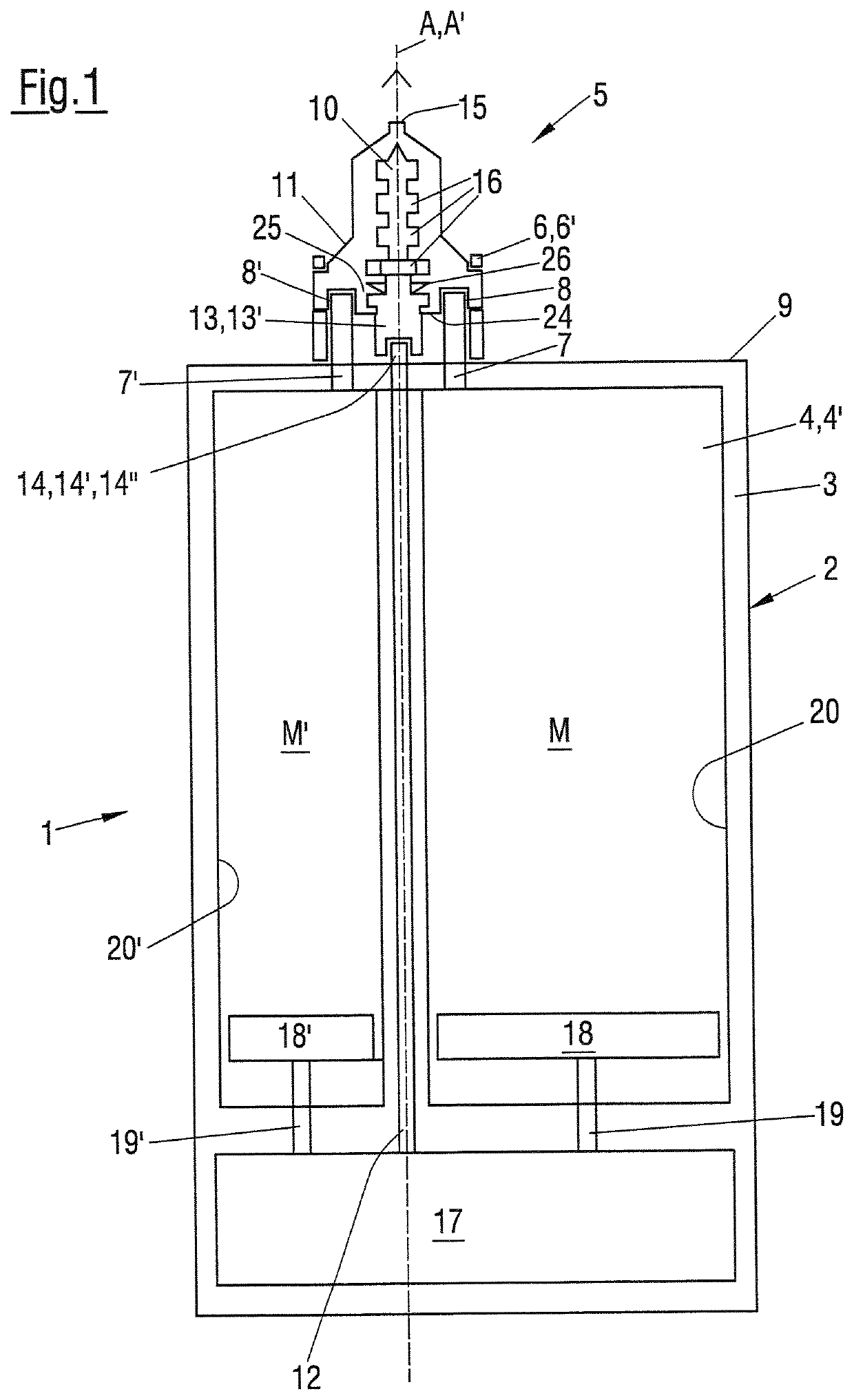
[0050]FIG. 1 shows a schematic sectional view of an automatic mixing unit (mixer) 1 as is used e.g. in dental surgeries to dispense multi-component materials then used to form e.g. dental imprints or molds of a patients' teeth. The automatic mixing unit 1 comprises a housing 2 having a cartridge receptacle 3 for a multicomponent cartridge 4, in the present instance a two-component cartridge 4′. A dynamic mixer 5 is connected to the two-component cartridge 4′ in a connection region 6 present in the region of the outlets 7, 7′ from the two-component cartridge 4′ and in the region of the inlets 8, 8′ of the dynamic mixer 5 at an end 9 of the housing 2.

[0051]In the present example the connection ...


PUM


Abstract

A dynamic mixer for mixing a multi-component material includes a mixing rotor capable of being rotated about an axis of rotation, the mixing rotor having a coupling socket configured at an end thereof. The coupling socket has a reception space configured to receive at least a part of a polygonal shaped coupling plug of a drive shaft to transfer torque from the drive shaft to the mixing rotor. The reception space has an inner length in the direction of the axis of rotation and has an inner surface extending over the inner length and surrounding the axis of rotation.

Description

CROSS-REFERENCE TO RELATED APPLICATION[0001]This application is a U.S. National Stage application of International Application No. PCT / EP2018 / 073331, filed Aug. 30, 2018, which claims priority to European Patent Application No. 17188867.0, filed Aug. 31, 2017, the contents of each of which are hereby incorporated herein by reference.BACKGROUNDField of the Invention[0002]The present invention relates to a dynamic mixer for mixing a multi-component material, the dynamic mixer generally comprises a mixing rotor that can be rotated about an axis of rotation, the mixing rotor having a coupling socket configured at an end thereof, wherein the coupling socket has a reception space configured to receive at least a part of a polygonal shaped coupling plug of a drive shaft in order to transfer torque from the drive shaft to the mixing rotor, wherein the reception space has an inner length in the direction of the axis of rotation and has an inner surface extending over the inner length and sur...

Claims


Application Information

Patent Timeline
Patent Type & Authority Applications(United States)
IPC IPC(8): B01F7/00B01F13/00B01F15/02
CPCB01F15/0237B01F7/00725B01F2215/0039B01F13/0023B01F2215/0027B01F2215/0431B01F7/00291F16D1/101F16D2001/102B01F27/213B01F2101/19B01F2101/2305B01F27/19B01F27/2123B01F27/88B01F27/1125B01F33/50112B01F35/7174
Inventor BICKER, RENE
Owner MEDMIX SWITZERLAND AG
Why Eureka
Try Eureka