Muzzle Brake

a technology of which is applied in the field of muzzle break, can solve the problems of not being able to achieve both tasks equally well, unable to provide a slight improvement in flash suppression over conventional muzzle break and compensator, and employing an effective method of expanding and cooling the escape gas, so as to reduce side concussion

Active Publication Date: 2015-10-29
PM RES INC
View PDF18 Cites 26 Cited by
  • Summary
  • Abstract
  • Description
  • Claims
  • Application Information

AI Technical Summary

Benefits of technology

[0009]It is another objective of the present invention to redirect expand, cool, and disrupt shock wave formation of the ex

Problems solved by technology

Many of these devices do an acceptable job of achieving one of these tasks, but none are able to achieve both tasks equally well.
However, since none of these devices employ an effective method of e

Method used


Image

  • Muzzle Brake
  • Muzzle Brake
  • Muzzle Brake

Examples


Embodiment Construction

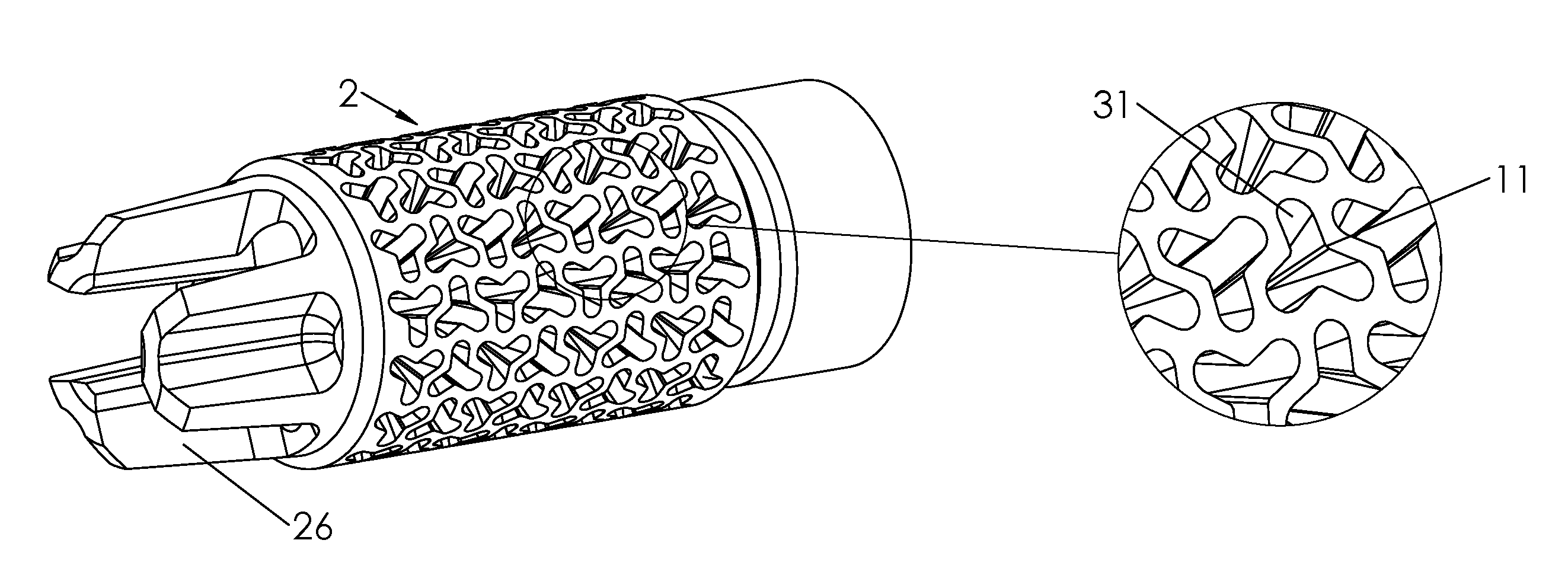
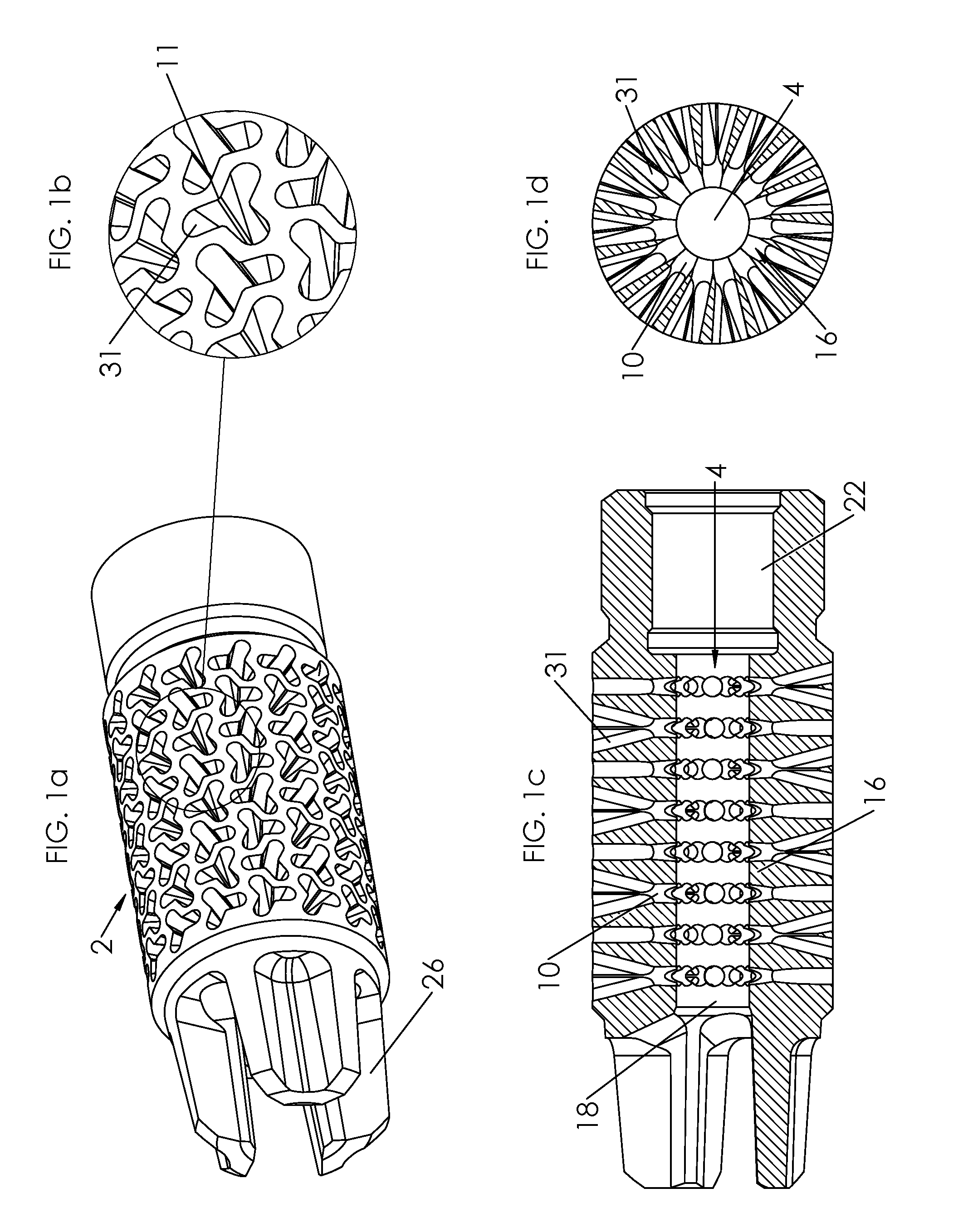
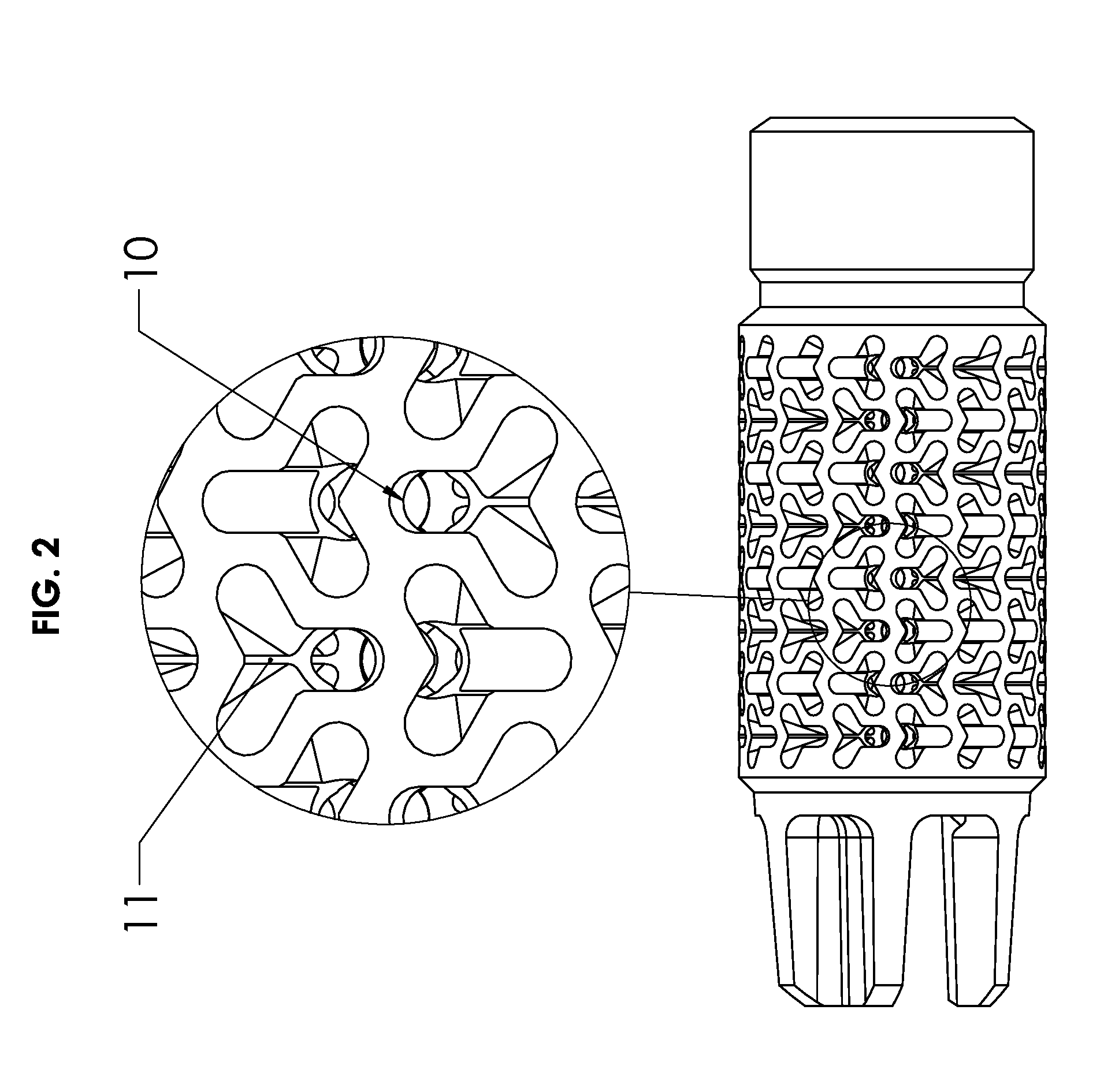
[0035]While this invention may be embodied in many different forms, as illustrated in FIGS. 1a-1d, FIG. 2, FIGS. 3a-3d, FIG. 4, and FIGS. 5a-5d. A preferred embodiment is shown in FIGS. 1a-1d, FIG. 2. This embodiment has a cylindrical body (2) having a coaxial passageway (4) preferably between 1.1 and 1.5 bullet calibers in diameter and preferably between 5 and 7 bullet calibers in length, forward of and communicating with a coaxial threaded bore (22) for attaching the muzzle device to the threaded muzzle of a firearm barrel. The coaxial passageway (4) communicates with the longitudinal front slots (26) through the coaxial exit hole (18), which is preferably the same diameter or smaller than the coaxial passageway (4). The coaxial passageway and the coaxial exit hole are sufficiently large to allow the passage of a fired bullet. When the firearm is fired, the bullet exits the muzzle of the gun and travels along the coaxial passageway (4) of the attached muzzle device and exits throu...


PUM


Abstract

A muzzle device that may be attached to the barrel of a forearm that includes structures which influence the flow characteristics of exhausting propellant gases for suppressing muzzle flash, counter acting the rearward and upward motion of the muzzle during firing, and reducing the concussion directed towards the shooter as well as personnel to the sides of the shooter.

Description

BACKGROUND OF THE INVENTION[0001]1. Field of the Invention[0002]The present invention generally relates to firearms and, more particularly, to a muzzle device that reduces the recoil, muzzle flash, and side concussion of a firearm allowing for better muzzle control, improved situational awareness of the shooter, and reduced visual signature to better conceal the shooter from enemy return fire.[0003]2. Description of Related Art[0004]Many muzzle brakes, compensators, and flash hiders have been developed over the years that either suppress muzzle flash or reduce and redirect recoil. Many of these devices do an acceptable job of achieving one of these tasks, but none are able to achieve both tasks equally well. Furthermore, in recent years there has been an increasing number of so called “multipurpose” muzzle devices introduced to the market that claim to increase muzzle control through recoil reduction and redirection, as well as reduce muzzle flash and excessive side concussion. Most...

Claims


Application Information

Patent Timeline
IPC IPC(8): F41A21/36F41A21/28
CPCF41A21/28F41A21/36F41A21/34
Inventor VOSSLER, STEPHEN PAUL
Owner PM RES INC
Why Eureka
Try Eureka