
Liquid ejecting apparatus

Active Publication Date: 2015-11-26
SEIKO EPSON CORP
View PDF1 Cites 16 Cited by
  • Summary
  • Abstract
  • Description
  • Claims
  • Application Information

AI Technical Summary

Benefits of technology

The invention is about a liquid ejecting apparatus that can efficiently collect any waste liquid that may be generated inside the apparatus. The technical effect is to improve the overall functionality and reliability of the apparatus.

Problems solved by technology

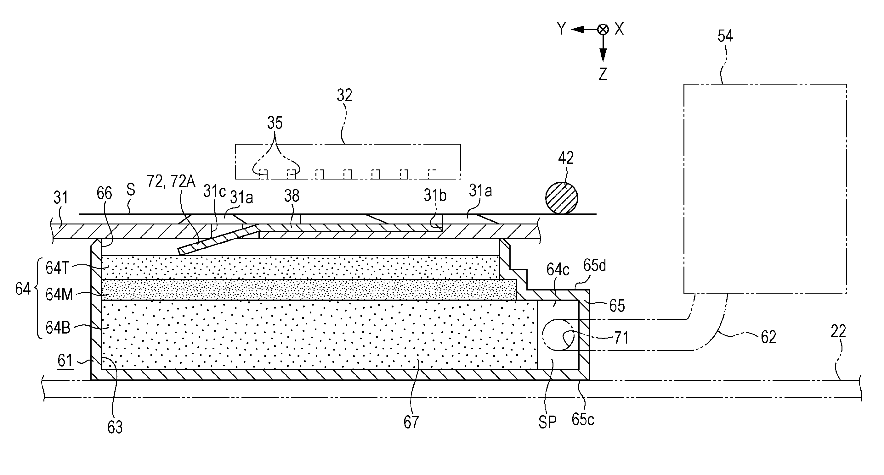
In this case, the problem is to efficiently collect the ink (the waste liquid) that is discharged through the grooves provided in the platen which is disposed in the transport path of the paper, and the ink (the waste liquid) that is discharged from the cap member which is disposed outside of the transport path of the paper.

Method used


Image

  • Liquid ejecting apparatus
  • Liquid ejecting apparatus
  • Liquid ejecting apparatus

Examples


Embodiment Construction

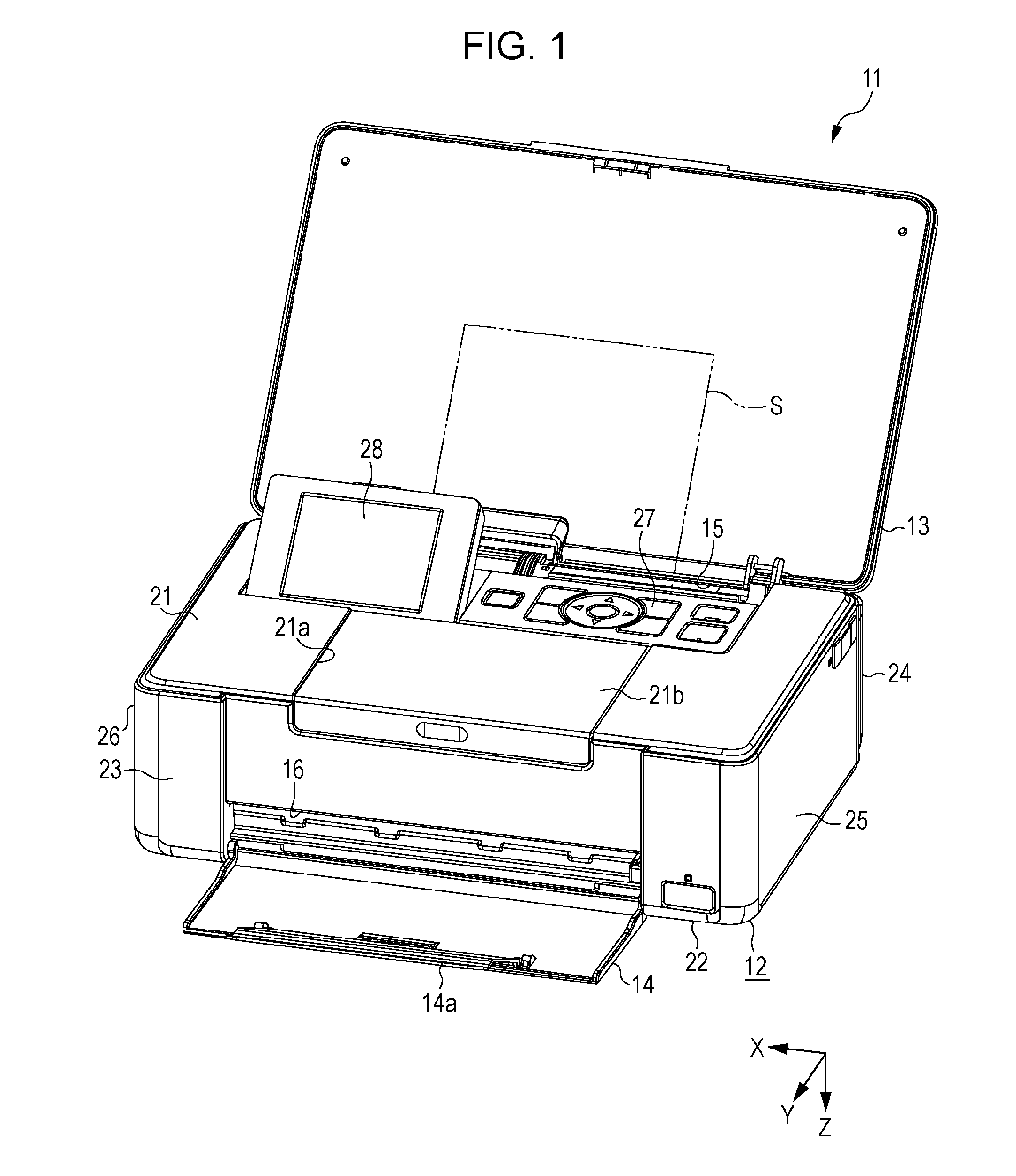
[0029]Hereinafter, description will be given of the embodiment of the liquid ejecting apparatus with reference to the drawings. An example of the liquid ejecting apparatus is an ink jet printer which performs recording (printing) by ejecting an ink, which is an example of the liquid, on to a medium such as paper.

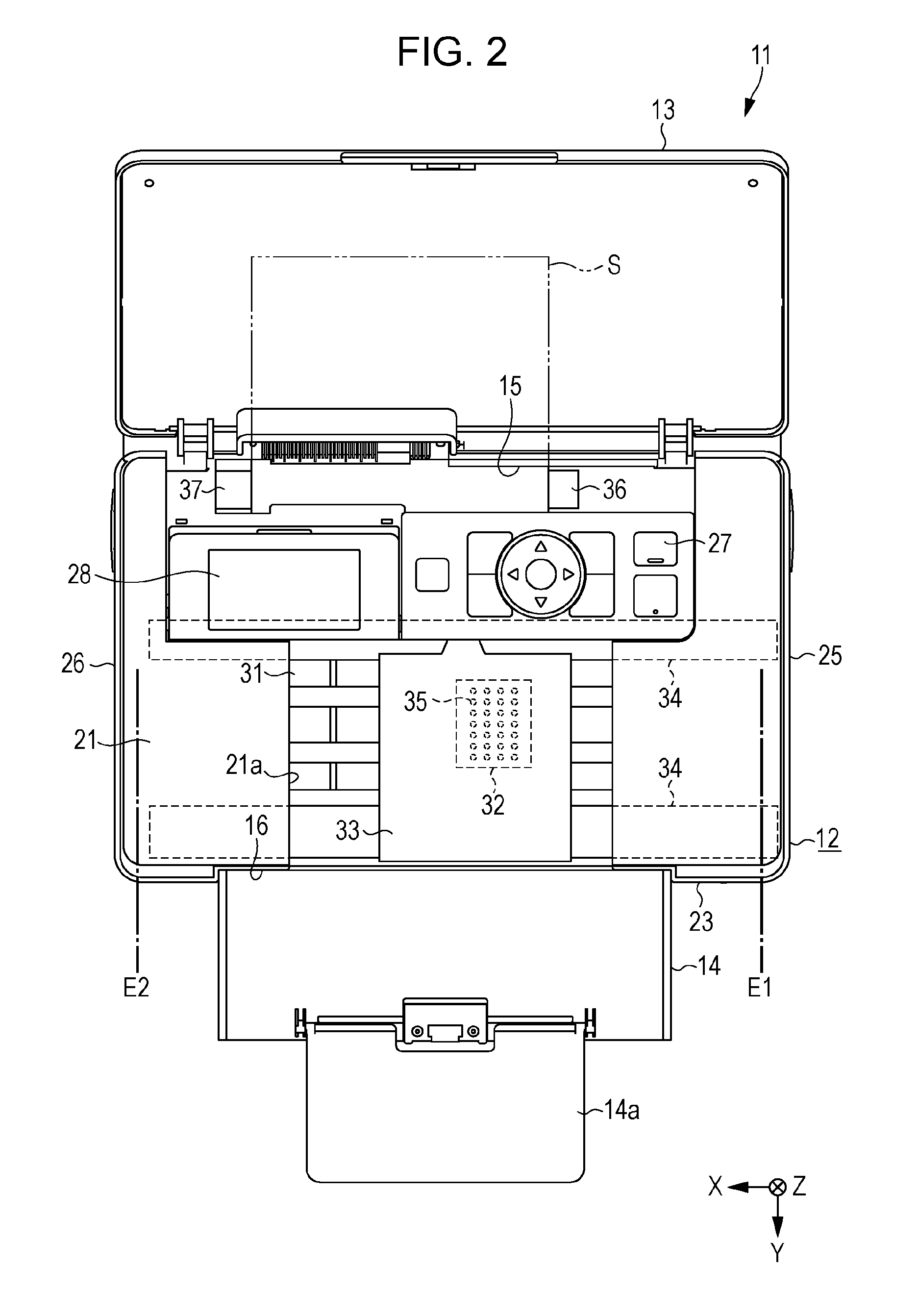
[0030]As illustrated in FIG. 1, a liquid ejecting apparatus 11 is provided with a rectangular box shaped housing section 12, a top lid 13, and a front lid 14. The top lid 13 is attached to be capable of moving rotationally in relation to the housing section 12, and the front lid 14 is similarly attached to be capable of moving rotationally in relation to the housing section 12. By moving rotationally to predetermined angles, the top lid 13 and the front lid 14 are disposed in closed positions overlapping the housing section 12, and open positions illustrated in FIG. 1.

[0031]When the top lid 13 is disposed in the open position, an insertion opening 15 for inserting a medium S...


PUM


Abstract

A liquid ejecting apparatus includes a liquid ejecting unit which ejects a liquid onto a medium being transported in a state in which an edge portion thereof is aligned with a second end side of a first end and the second end in a width direction intersecting a transport direction of a transport path, a first reception section which receives the liquid discharged from the liquid ejecting unit as a waste liquid, a second reception section which receives the liquid ejected from the liquid ejecting unit toward the edge portion and is not received by the medium as the waste liquid, and a waste liquid holding section which holds the waste liquid, the waste liquid holding section including an inlet to guide the waste liquid received by the first reception section.

Description

BACKGROUND[0001]1. Technical Field[0002]The present invention relates to a liquid ejecting apparatus such as a printer.[0003]2. Related Art[0004]An example of the liquid ejecting apparatus is an ink jet printer which performs borderless printing in which a margin in not left at edge portions of paper by ejecting an ink from nozzles which are provided in a liquid ejecting head such that a margin is not left at the edge portions of the paper. There is a printer, of those that perform borderless printing, in which grooves are provided in a platen that supports the paper, a waste liquid tray is provided underneath the platen, ink droplets that fall outside of the edge portions of the paper are received by an absorbent material that is disposed in the grooves, and the ink that is received by the absorbent material is guided into the waste liquid tray (for example, JP-A-2004-142125).[0005]In the printer described above, there is a case in which the ink is discharged from the nozzles into ...

Claims


Application Information

Patent Timeline
IPC IPC(8): B41J2/165
CPCB41J2/16523B41J2/16508B41J2/1652B41J2/16532B41J2/1721B41J29/13
Inventor SHIMAZU, MASAMITSU
Owner SEIKO EPSON CORP
Learn More