Atomizing head, atomizer and electronic cigarette having same

a technology of atomizer and electronic cigarette, which is applied in the field of electronic cigarettes, can solve the problems of tobacco liquid leaking from the liquid blocking element, and achieve the effect of preventing the leakage of tobacco liquid

Inactive Publication Date: 2016-01-07
SHENZHEN FIRST UNION TECH CO LTD
View PDF10 Cites 84 Cited by
  • Summary
  • Abstract
  • Description
  • Claims
  • Application Information

AI Technical Summary

Problems solved by technology

However, in the atomizer, the tobacco liquid may leak from the liquid blocking element.

Method used


Image

  • Atomizing head, atomizer and electronic cigarette having same
  • Atomizing head, atomizer and electronic cigarette having same
  • Atomizing head, atomizer and electronic cigarette having same

Examples


##s embodiment

FIRS EMBODIMENT

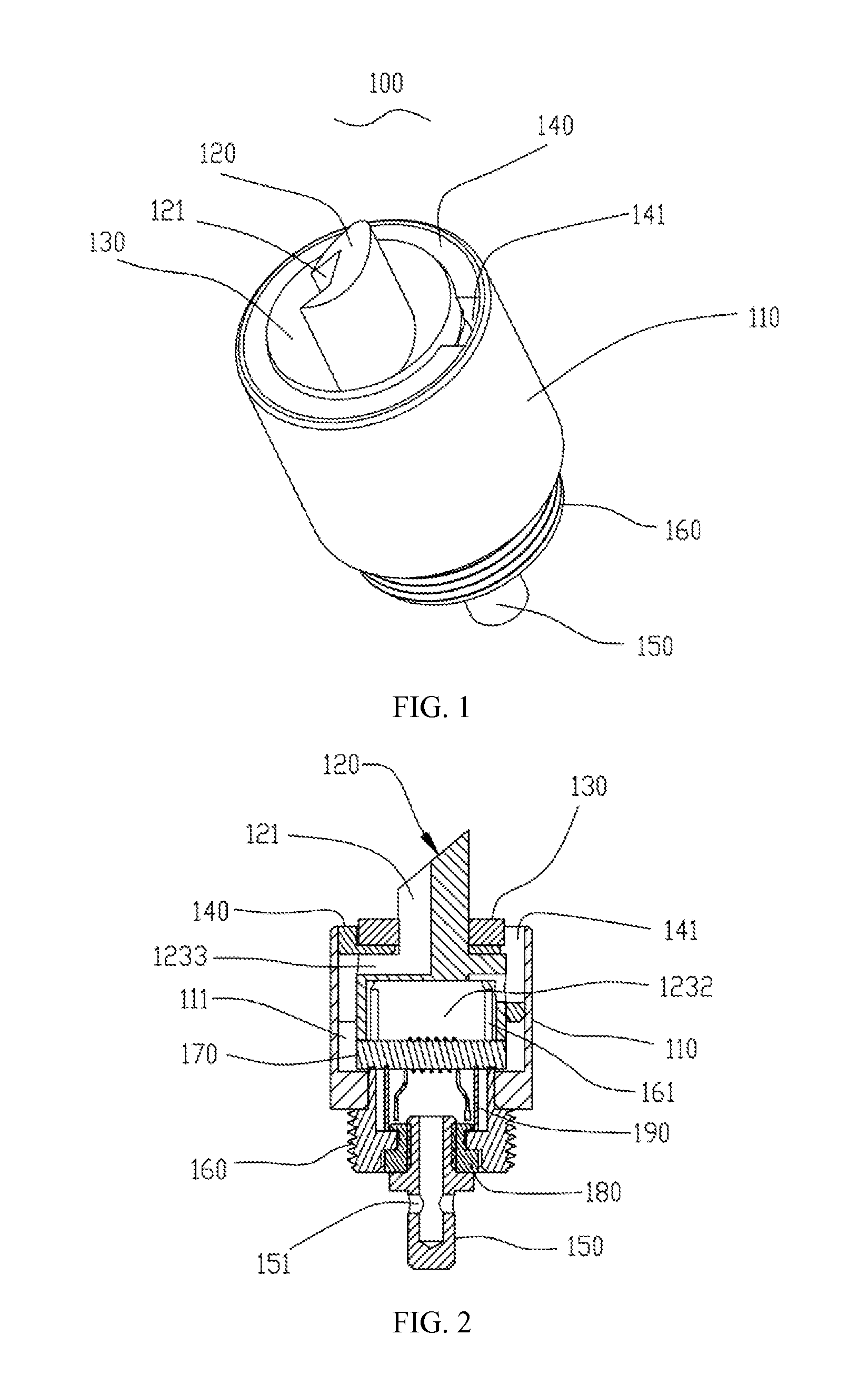
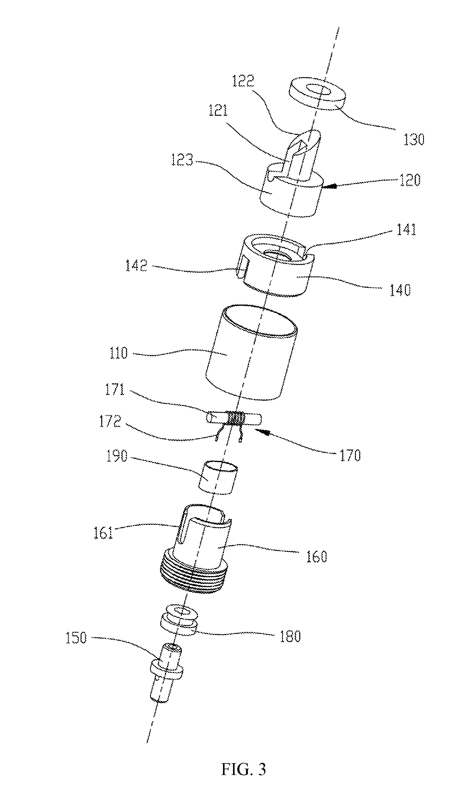
[0032]Referring to FIGS. 1-2, an atomizing head 100 for an electronic cigarette is shown. The atomizing head 100 includes a holder 110, an air inlet 151, an air outlet 141, a piercing element 120, a first electrode 160, a second electrode 150, a buffer chamber 111, an atomizing cavity 1232, and an atomizing component 170. The piercing element 120 is configured for pricking a liquid supply. The atomizing component 170 is configured (i.e., structured and arranged) for absorbing heating tobacco liquid in the buffer chamber 111 and heating the tobacco liquid. Both of the air outlet 141 and the air inlet 151 are in communication with the atomizing cavity 1232. The air inlet 151 is defined in the second electrode 150. The first electrode 160 and the second electrode 150 are configured for connecting to an external power supply. An insulating body 180 is sandwiched between the first electrode 160 and the second electrode 150. The piercing element 120 includes a liquid inlet ...

second embodiment

[0041]Referring to FIGS. 7-8, an atomizing head 300 according to a second embodiment is shown. The atomizing head 300 includes a holder 310, an air inlet 351, an air outlet 331, a piercing element 320, a first electrode 360, a second electrode 350, a buffer chamber 311, an atomizing cavity 3232, and an atomizing component 370. The air outlet 331 and the air inlet 351 are all in communication with the atomizing cavity 3232. The air inlet 351 is defined in the second electrode 350. An insulating body 380 is arranged between the first and the second electrodes 350, 360. The piercing element 320 defines a liquid inlet 321. As shown in FIGS. 8 and 11, the air outlet 331 and the liquid inlet 3321 are arranged on one side of the atomizing head 300.

[0042]Referring to FIGS. 9-10, the piercing element 320 includes a connecting part 323 and a piercing part 322. The liquid inlet 321 is defined in the piercing part 322. The connecting part 323 defines an air hole 3231 in a top surface. The air h...

third embodiment

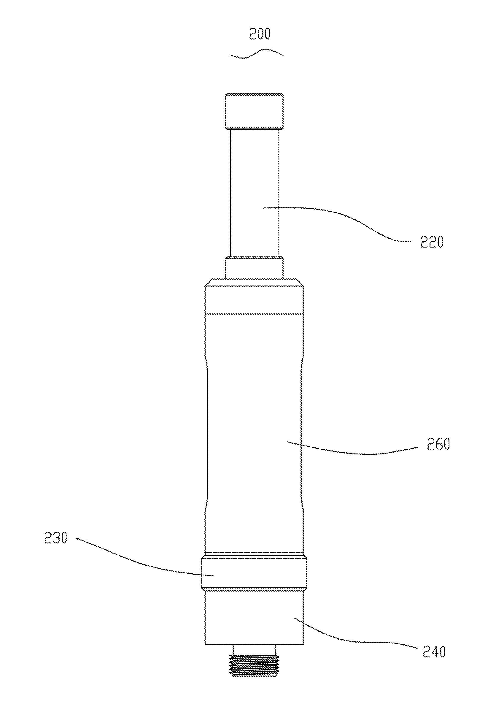
[0046]Referring to FIGS. 14-15, an atomizer 200 for an electronic cigarette is shown. The atomizer 200 includes an atomizing head 100 according to the first embodiment, an atomizing tube 210, a mouthpiece 220, a connector 230, and a threaded electrode 240. The mouthpiece 220 and the connector 230 are arranged at two opposite ends of the atomizing tube 210. The threaded electrode 240 is adapted for connecting with an external power supply. The atomizing tube 210 defines an accommodating space for receiving a liquid supply. In the present embodiment, the liquid supply is a liquid cup 270 made of transparent material.

[0047]Referring to FIG. 16, the atomizing head 100 is detachably engaged in the connector 230.

[0048]Referring to FIGS. 16-18, the connector 230 includes a plurality of first screw threads 231, and a plurality of second screw threads 231. The threaded electrode 240 includes a plurality of third screw threads 241, a plurality of fourth screw threads 242, and a plurality of f...


PUM


Abstract

An exemplary atomizer includes an atomizing tube and an atomizing head. The atomizing tube defines a space configured for receiving a liquid supply filled with tobacco liquid. The atomizing head includes a holder, an air inlet, an air outlet, a piercing element, a buffer chamber, an atomizing cavity, and an atomizing component. The piercing element is configured for piercing the liquid supply. The piercing element defines a liquid inlet. The buffer chamber is configured for storing the tobacco liquid flowed from the liquid supply via the liquid inlet after the liquid supply is pierced. The liquid inlet is in communication with the buffer chamber and the liquid supply. Both of the air inlet and the air outlet communicates with the atomizing cavity. The atomizing component is configured for absorbing the tobacco liquid in the buffer chamber and heating the tobacco liquid to vaporize.

Description

TECHNICAL FIELD[0001]The present invention relates to electronic cigarettes, and particularly to an atomizing head, an atomizer and an electronic cigarette using same.BACKGROUND ART[0002]In a typical atomizer with a piercing structure, the piercing structure includes a hollow liquid passage. After the piercing structure pricks a liquid supply, tobacco liquid flows to an atomizing cavity through the liquid passage. To prevent liquid leakage, a liquid blocking element is provided at the bottom of the liquid passage. The liquid blocking element is configured for absorbing and storing the tobacco liquid flowed from the liquid passage. However, in the atomizer, the tobacco liquid may leak from the liquid blocking element.[0003]What is needed, therefore, is an atomizing head, an atomizer and an electronic cigarette using same, which can overcome the above shortcomings.SUMMARY[0004]An exemplary atomizer includes an atomizing tube and an atomizing head. The atomizing tube defines a space co...

Claims


Application Information

Patent Timeline
Patent Type & Authority Applications(United States)
IPC IPC(8): A24F40/10A24F40/485A24F40/50
CPCA24F47/008A24F40/10A24F40/50A24F40/485
Inventor LI, YONGHAIXU, ZHONGLIHE, YOULIN
Owner SHENZHEN FIRST UNION TECH CO LTD
Why Eureka
Try Eureka