Arbitrary Surface Printing Device for Untethered Multi-Pass Printing

a multi-pass printing and arbitrary surface technology, applied in printing, typewriters, power drive mechanisms, etc., can solve the problems of heavy devices, bulky conventional electrical printers, and common limitations of the foregoing printer configurations

Inactive Publication Date: 2016-01-28
PRIYADARSHI ROHIT
View PDF1 Cites 11 Cited by
  • Summary
  • Abstract
  • Description
  • Claims
  • Application Information

AI Technical Summary

Problems solved by technology

However, all of the foregoing printer configurations are subject to common limitations: immobility and inflexibility with respect to print surface.
Conventional electrical printers are bulky, heavy devices that must remain in a fixed location and orientation to ensure proper operation.
Electrical printers are renowned for experiencing “jams” due to slight deformities in paper being moved throughout the housing, or even simply due to slight irregularities in operation even when working with a “perfect” sheet of paper.
Mechanical printers are not necessarily subject to the jamming problems common to electrical printers, but may experience similar issues (e.g. problems with the motion of the print head / shutter mechanism on an address label) in some cases.
However, mechanical printers are also subject to mobility limitations, relying entirely on the user to position and perform the printing operation manually.
Conventional mechanical printers are not capable of printing predefined patterns with precision and complexity characteristic of electrical printers, instead relying on the skill of the user to accomplish any detailed or custom-tailored printing.
However, 3D printers are even more sensitive to location and orientation, and often orders of magnitude larger and heavier than conventional electrical printers, making these configurations even less capable of mobility and mobile printing.
Existing untethered printers such as disclosed in the above references are not capable of performing high-precision or multi-pass printing, especially using different colors and / or printing materials due to lack of synchronization and alignment between different passes.
Further, it is typically impossible to remove the arbitrary print surface where printing is desired and insert it in a conventional printer.

Method used


Image

  • Arbitrary Surface Printing Device for Untethered Multi-Pass Printing
  • Arbitrary Surface Printing Device for Untethered Multi-Pass Printing
  • Arbitrary Surface Printing Device for Untethered Multi-Pass Printing

Examples


Embodiment Construction

[0027]The following description is made for the purpose of illustrating the general principles of the present invention and is not meant to limit the inventive concepts claimed herein. Further, particular features described herein can be used in combination with other described features in each of the various possible combinations and permutations.

[0028]Unless otherwise specifically defined herein, all terms are to be given their broadest possible interpretation including meanings implied from the specification as well as meanings understood by those skilled in the art and / or as defined in dictionaries, treatises, etc.

[0029]It must also be noted that, as used in the specification and the appended claims, the singular forms “a,”“an” and “the” include plural referents unless otherwise specified.

[0030]The following description discloses several preferred embodiments of magnetic storage systems, as well as operation and / or component parts thereof.

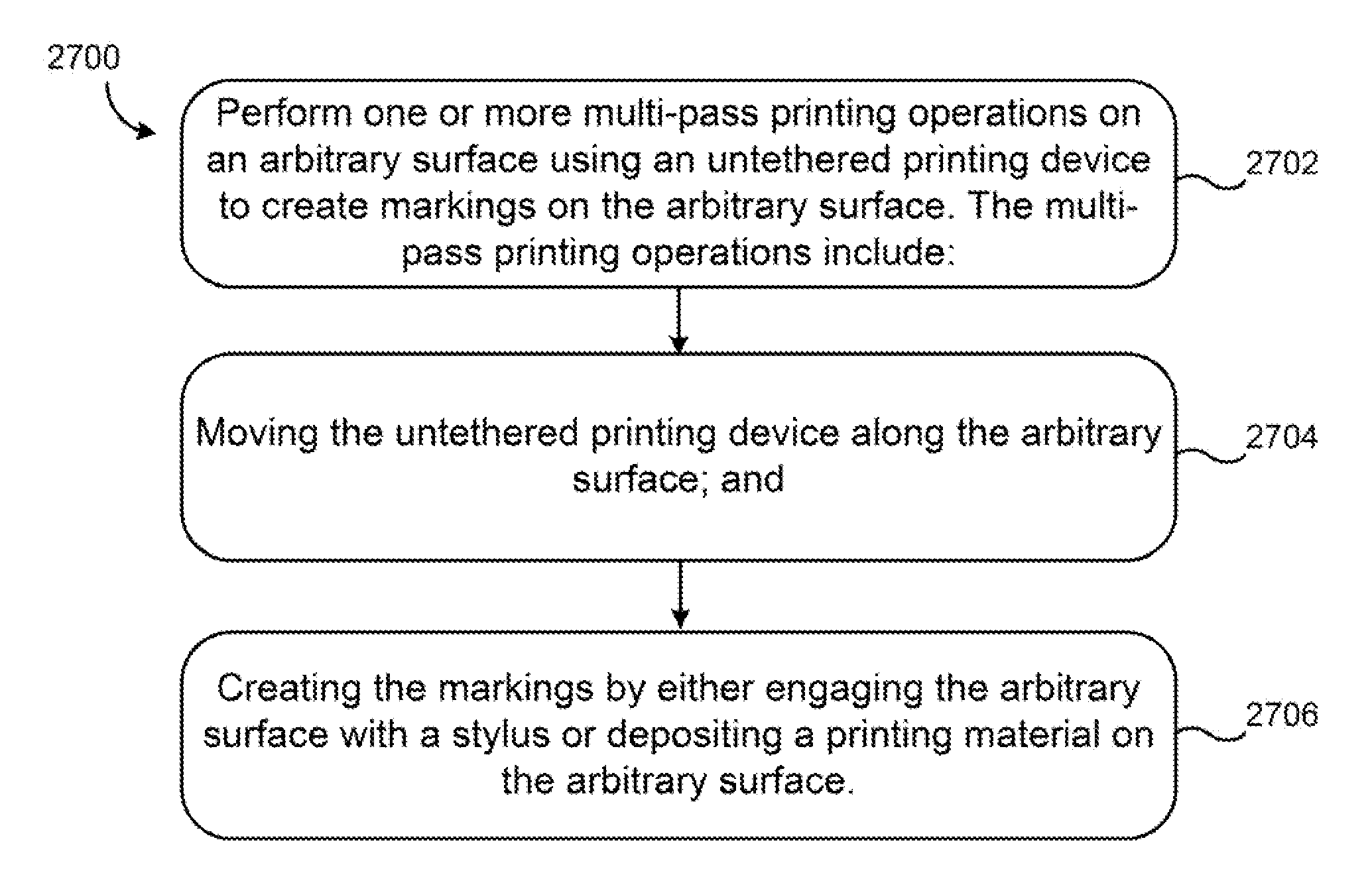
[0031]In one general embodiment, an unte...


PUM


Abstract

An untethered, arbitrary-surface printing device includes a housing, a print head, positioning means, locomotive means, and sensors configured to perform multi-pass high-precision printing (i.e. at least 300 dots per inch) on nearly any surface texture.

Description

RELATED APPLICATIONS[0001]This application is a divisional of, and claims the benefit of priority to U.S. patent application Ser. No. 14 / 584,941, entitled “ARBITRARY-SURFACE PRINTING DEVICE FOR UNTETHERED MULTI-PASS PRINTING” filed Dec. 29, 2014, which claims priority to U.S. Provisional Patent Application No. 61 / 921,408, entitled “Untethered Arbitrary Surface Printing Device” filed Dec. 27, 2013. All subject matter disclosed in any of the aforementioned patent applications is herein incorporated by reference.FIELD OF INVENTION[0002]The present invention relates to printing, and more particularly, this invention relates to using an untethered device, i.e. a free-moving device, to accomplish printing on variable surfaces and textures.[0003]As well-known in the art, an electric printer generally comprises a housing, a print head, a cartridge or reservoir for storing and dispensing printing material, e.g., ink, a tray for storing paper, means for moving the paper throughout the housing...

Claims


Application Information

Patent Timeline
Patent Type & Authority Applications(United States)
IPC IPC(8): B41J25/00
CPCB41J25/006B41J2/125B41J3/4073B41J29/38B41J29/00
Inventor PRIYADARSHI, ROHIT
Owner PRIYADARSHI ROHIT
Why Eureka
Try Eureka