Head-up display apparatus

a display apparatus and head-up technology, applied in the direction of dashboard fitting arrangements, planar/plate-like light guides, instruments, etc., can solve the problems of difficulty for a driver who receives a warning to immediately, and the driver may not cope with dangerous objects, etc., to brighten the first diffusion unit and the second diffusion unit.

Active Publication Date: 2016-02-18
DENSO CORP
View PDF8 Cites 3 Cited by
  • Summary
  • Abstract
  • Description
  • Claims
  • Application Information

AI Technical Summary

Benefits of technology

[0012]According to the head-up display apparatus, when the light emission unit having the first reflection unit operates, the light is reflected on the first reflection unit, and reaches the first side end surface of the combiner, and it may be possible to brighten the first diffusion unit disposed on the first side end surface. When the light emission unit having the second reflection unit operates, the light is reflected on the second reflection unit, and reaches the second side end surface, and it may be possible to brighten the second diffusion unit. Since it may be possible for the driver to intuitively recognize a direction along which the dangerous object such as a pedestrian and an obstacle is present according to which side of the combiner is brightened, it may be possible for the driver to cope with the dangerous object such as the pedestrian and the obstacle immediately.

Problems solved by technology

However, in any technologies, there is a difficulty that it may be difficult for a driver who receives a warning to immediately cope with a dangerous object such as a pedestrian, an obstacle.
The driver may not cope with the dangerous object, immediately.

Method used


Image

  • Head-up display apparatus
  • Head-up display apparatus
  • Head-up display apparatus

Examples


first embodiment

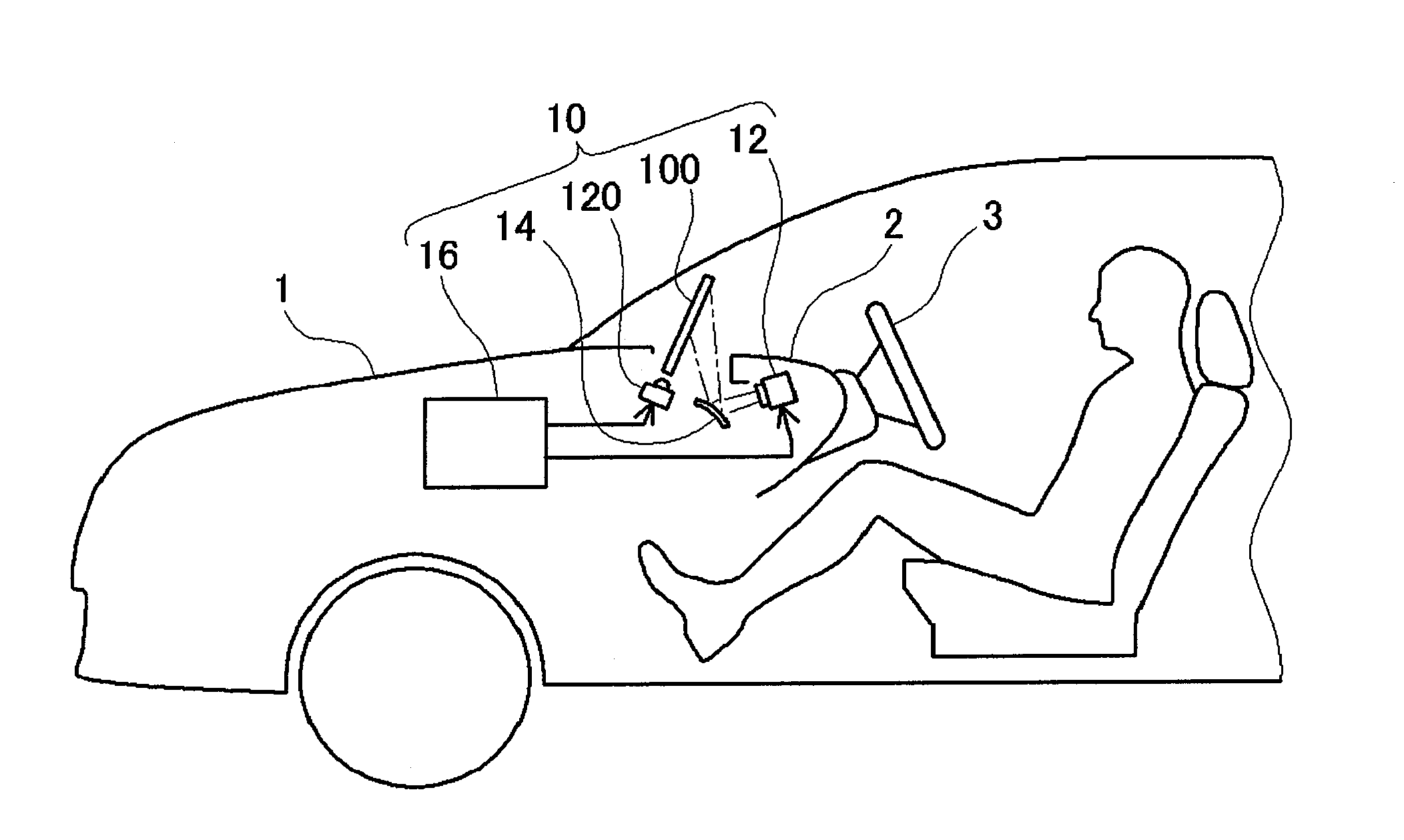
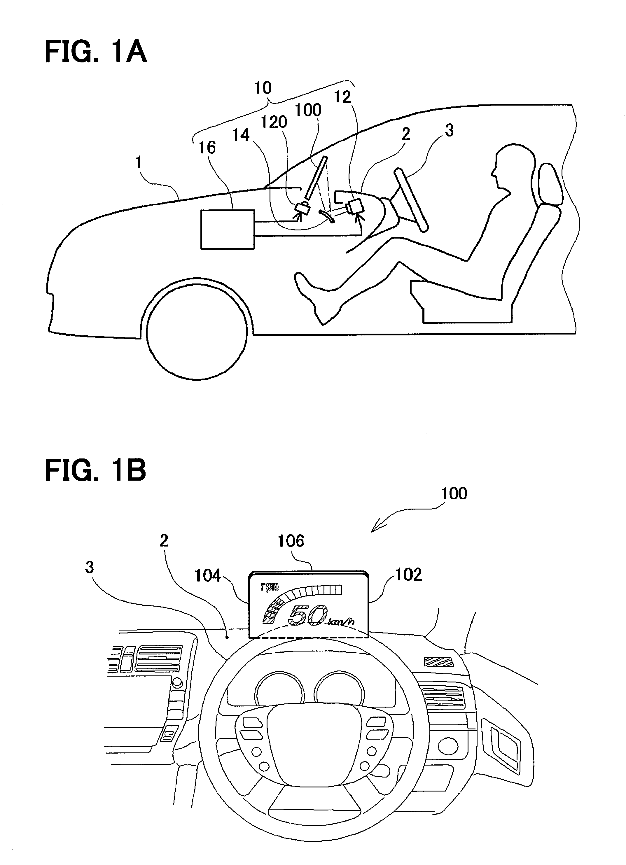
[0027]A first embodiment of the present disclosure will be described with referring to the drawings. FIG. 1A and FIG. 1B illustrate a head-up display apparatus 10 according to the present embodiment, mounted to a dashboard 2 of a vehicle 1. As illustrated in FIG. 1A, the head-up display apparatus 10 according to the present embodiment includes a combiner 100 to which an image is projected and displayed, an image projection unit 12 that projects the image displayed to the combiner 100, a convex mirror 14 that reflects the image projected from the image projection unit 12 toward the combiner 100, an LED unit 120 that emits a light from an end surface of the combiner 100 toward an interior of the combiner 100, and a control device 16 that controls an operation of the image projection unit 12 and the LED unit 120.

[0028]The combiner 100 is a plate member made of a transparent material such as acrylic resin, and a driver of the vehicle 1 can visually recognize a front view of the vehicle ...

first modification

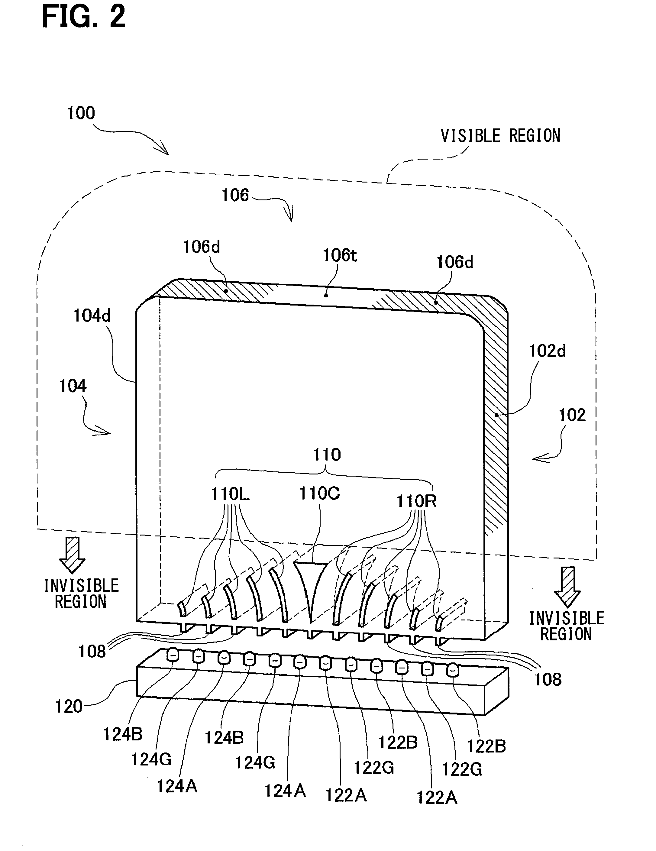
[0064]In the first embodiment, the right side end surface 102, the left side end surface 104, and the upper end surface 106 of the combiner 100 are formed at right angles to a display surface (a surface to which an image is projected) of the combiner 100. Alternatively, as illustrated in FIG. 8, a right side end surface 102, a left side end surface 104, and an upper end surface 106 of the combiner 100 may be formed obliquely toward a driver. In this case, directions toward which the right side end surface 102, the left side end surface 104, and the upper end surface 106 are inclined may be inclined in directions in which the driver can visually recognize the end surfaces, directly or may be inclined in opposite directions. The directions may be inclined in directions in which the driver can visually recognize the end surfaces through the transparent combiner 100 although the driver cannot visually recognize the end surfaces directly.

[0065]For example, when the right side end surface...

second modification

[0067]In the present embodiment and above modification, the portions of the right side end surface 102, the left side end surface 104, and the upper end surface 106 of the combiner 100, which are subjected to emboss processing, irregularly reflect the light. The emboss processing may not be required as long as the light that reaches the right side end surface 102, the left side end surface 104, or the upper end surface 106 can be irregularly reflected.

[0068]For example, a light diffusion member made of a transparent material in which fine particles that scatter the light are dispersed may be disposed on the end surfaces of the combiner 100.

[0069]FIG. 9 illustrates a second modification in which a light diffusion member is provided to the end surfaces of the combiner 100. In this example, a right side light diffusion member 112 is fitted to an area extending from the right side end surface 102 to the right side of the upper end surface 106 in the combiner 100. A left side light diffu...


PUM


Abstract

A head-up display apparatus includes light emission units, a first reflection unit, a second reflection unit, a first diffusion unit, a second diffusion unit, and a driver unit. The light emission units are disposed along one end surface of an upper or lower end surface of a combiner, and emit light. The first reflection unit is disposed to a part of the light emission units, and reflects the light. The second reflection unit is disposed to a part of the light emission units, and reflects the light. The first diffusion unit is disposed in the first side end surface, and diffuses the light. The second diffusion unit is disposed in the second side end surface, and diffuses the light. The driver unit selectively drives one of the light emission unit, and causes to emit the light. The combiner includes an invisible region.

Description

CROSS REFERENCE TO RELATED APPLICATION[0001]This application is based on Japanese Patent Application No. 2013-87914 filed on Apr. 18 2013, the disclosure of which is incorporated herein by reference.TECHNICAL FIELD[0002]The present disclosure relates to a head-up display apparatus that projects an image to a transparent plate member disposed in front of a driver seat to display the image superimposed to a scenery in front of the driver seat.BACKGROUND ART[0003]As a technology enabling various information to be provided to a driver in a vehicle without moving the line of sight from a front, a head-up display apparatus projects an image to a transparent plate member that is called a combiner and enables the image to be displayed superimposed to a front view.[0004]Information such as a vehicle speed is normally displayed on the combiner of the head-up display apparatus. When a dangerous object such as a pedestrian or an obstacle is detected, the head-up display apparatus displays a fac...

Claims


Application Information

Patent Timeline
Patent Type & Authority Applications(United States)
IPC IPC(8): B60K37/02G02B27/01
CPCB60K37/02G02B27/0101B60K2350/965G02B2027/013B60K2350/1096B60K2350/1056G02B2027/0141B60K2350/2008B60K35/00B60K37/04B60K2370/15B60K2370/1529B60K2370/186B60K2370/188B60K2370/193B60K2370/332B60K2370/336B60K2370/338B60K2370/66B60K2370/6992G02B5/02G02B6/0018G02B2027/0118
Inventor INOMATA, MAKOTO
Owner DENSO CORP
Why Eureka
Try Eureka