Laptop carry on luggage tray

a luggage tray and carry-on technology, applied in the direction of trays, beds, other accessories, etc., can solve the problems of luggage being a liability, inconvenience, delay, frustration, etc., and affecting the service life of passengers,

Inactive Publication Date: 2016-03-24
UNDESSER JOHN
View PDF11 Cites 9 Cited by
  • Summary
  • Abstract
  • Description
  • Claims
  • Application Information

AI Technical Summary

Problems solved by technology

Consider that each year, more than three million articles of luggage are lost by airline travelers (which is to say lost by the airlines) leading not only to the loss of valuables, from personal jewelry to business documents, but to inconvenience, delay, and frustration.
In the world of modern travel, luggage is a liability.

Method used


Image

  • Laptop carry on luggage tray
  • Laptop carry on luggage tray
  • Laptop carry on luggage tray

Examples


Embodiment Construction

[0033]While the present disclosure is susceptible of embodiment in various forms, there is shown in the drawings and will hereinafter be described one or more embodiments with the understanding that the present disclosure is to be considered illustrative only and is not intended to limit the disclosure to any specific embodiment described or illustrated.

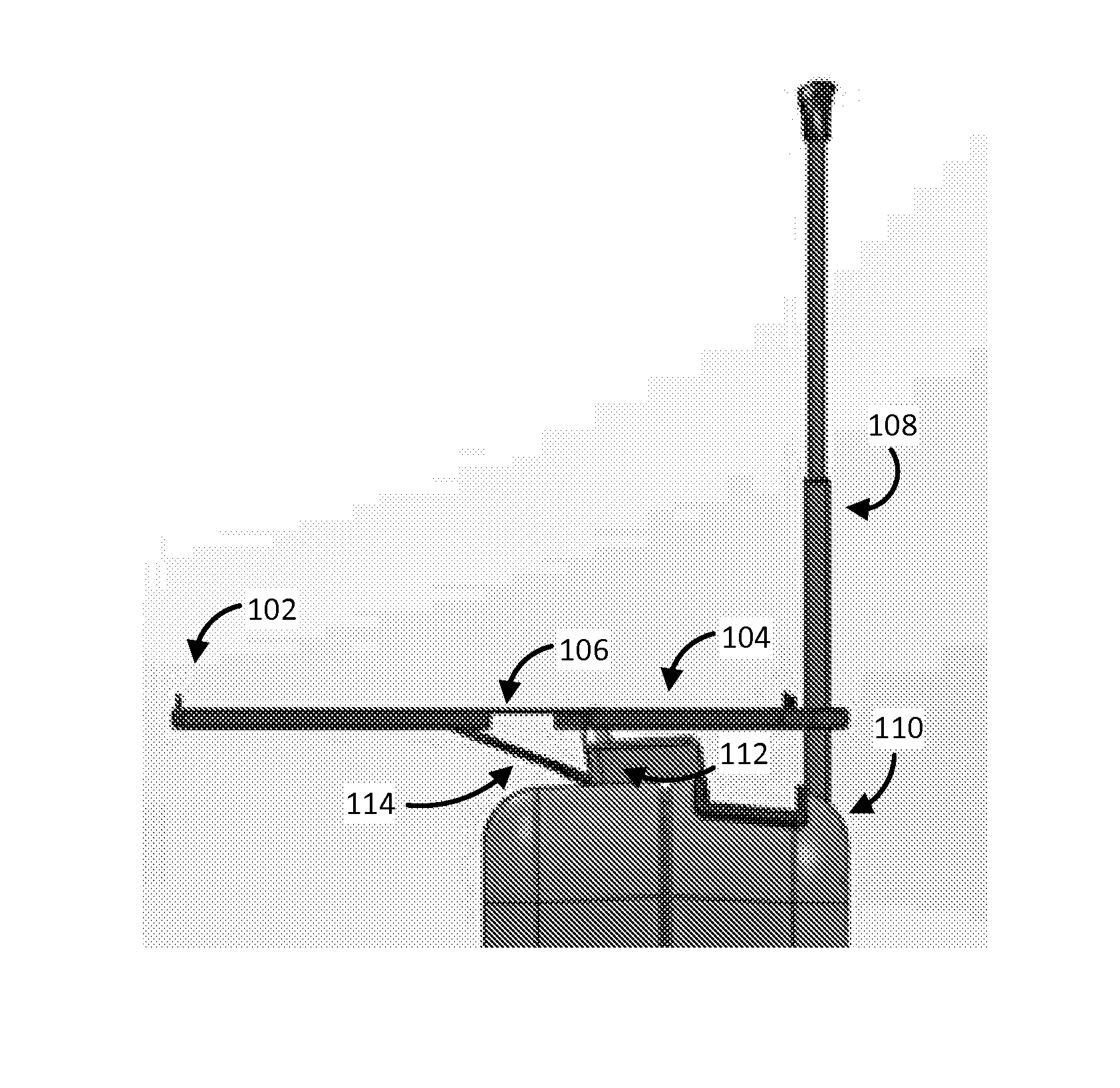
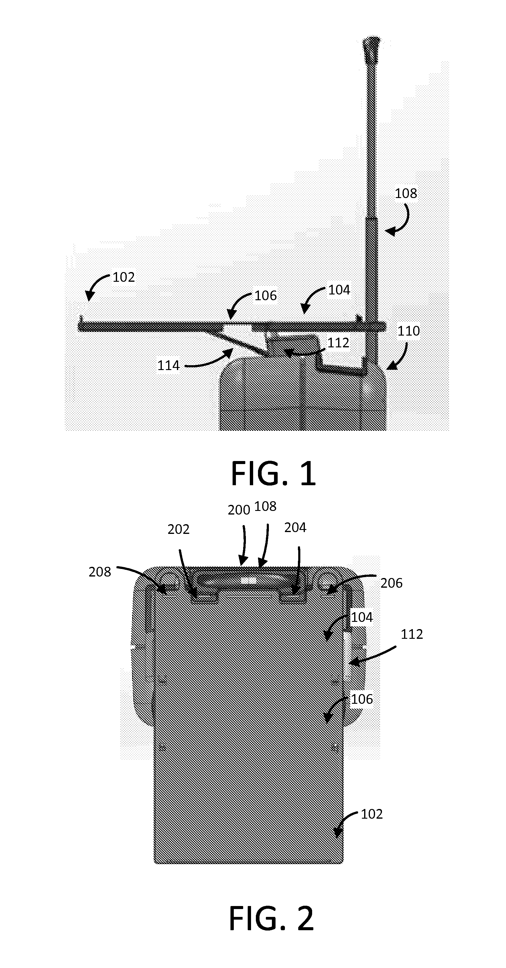
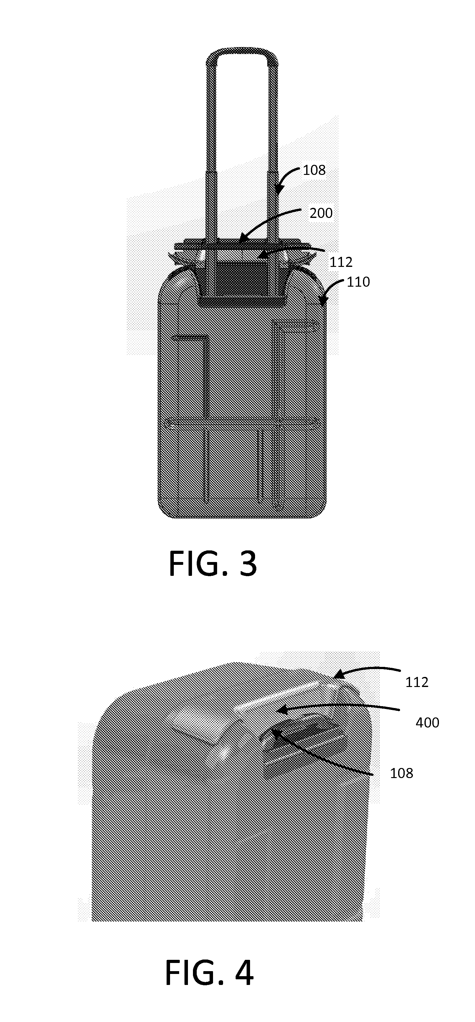
[0034]FIG. 1 depicts a shelf positioned on the arm of a bag of luggage. The shelf 100 include a front plate 102, a back plate 104 and a connection portion 106. A back portion of the back plate 104 connects to the arms 108 of the luggage 110 to support the shelf 100. A support unit 112 on the side of the shelf 100 facing the luggage 110 engages both the lower surface of the back plate 104 of the shelf 100 and a top surface of the luggage 110. An extension unit 114 extends from a side of the support unit 112 to the lower surface of the front plate 102. The extension unit 114 may be made of a flexible material, such as plastic or metal....


PUM


Abstract

A piece of luggage including an arm extending out of the luggage, a shelf hingedly connected to the arm, a support unit hingedly attached to a top surface of the luggage, where the support unit is positioned between the shelf and the luggage when the shelf if fully extended.

Description

RELATED APPLICATIONS[0001]This application is a non-provisional patent application that claims the benefit of and the priority from U.S. Provisional Patent Application No. 62 / 054,812, filed Sep. 24, 2014, titled LAPTOP CARRY ON.BACKGROUND[0002]Travel, for much of human history, was luxury and delight, an extravagance limited to the upper classes—or a hardship undertaken by poor but hopeful lower-class immigrants or refugees. Not so many generations past, people with the money and time could travel to Europe by Canard liner, hauling along three-months' worth of clothes in a couple of steamer trunks the size of office desks_No more. These days, travel is less pleasure than harrowing necessity for much of the working world, and traveling light has become a definite virtue. Consider that each year, more than three million articles of luggage are lost by airline travelers (which is to say lost by the airlines) leading not only to the loss of valuables, from personal jewelry to business d...

Claims


Application Information

Patent Timeline
Patent Type & Authority Applications(United States)
IPC IPC(8): A47B23/06A45C9/00A45C13/28A47B1/04A47B23/00
CPCA47B23/06A47B1/04A45C2011/003A45C13/28A45C9/00A47B23/001A45C13/26
Inventor UNDESSER, JOHN
Owner UNDESSER JOHN
Why Eureka
Try Eureka