Method and apparatus for producing an acoustic field

a technology of acoustic field and acoustic field, which is applied in the direction of instruments, measurement devices, computing, etc., can solve the problems of limitations of known systems for producing acoustic field using control points, and achieve the effect of improving the power output efficiency of the array and easy to specify the augmentation of the matrix

Active Publication Date: 2016-05-05
ULTRAHAPTICS IP LTD
View PDF8 Cites 54 Cited by
  • Summary
  • Abstract
  • Description
  • Claims
  • Application Information

AI Technical Summary

Benefits of technology

[0041]The advantage of performing a regularisation step is that this can improve the power output efficiency of the array by increasing the average amplitude of the transducers so that more of them are on at a higher amplitude. For example, to avoid a situation where one transducer is on at 100% and all of the others ar...

Problems solved by technology

However, known systems for producing an acoustic field using control p...

Method used


Image

  • Method and apparatus for producing an acoustic field
  • Method and apparatus for producing an acoustic field
  • Method and apparatus for producing an acoustic field

Examples


Embodiment Construction

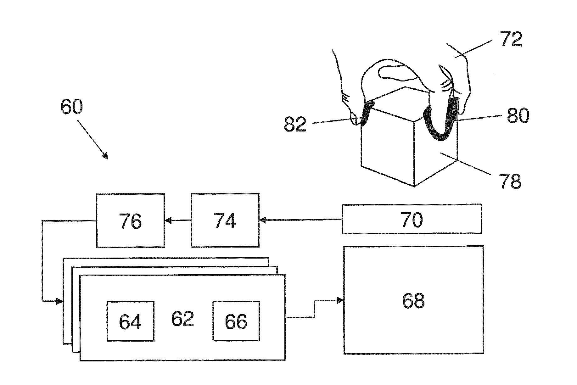
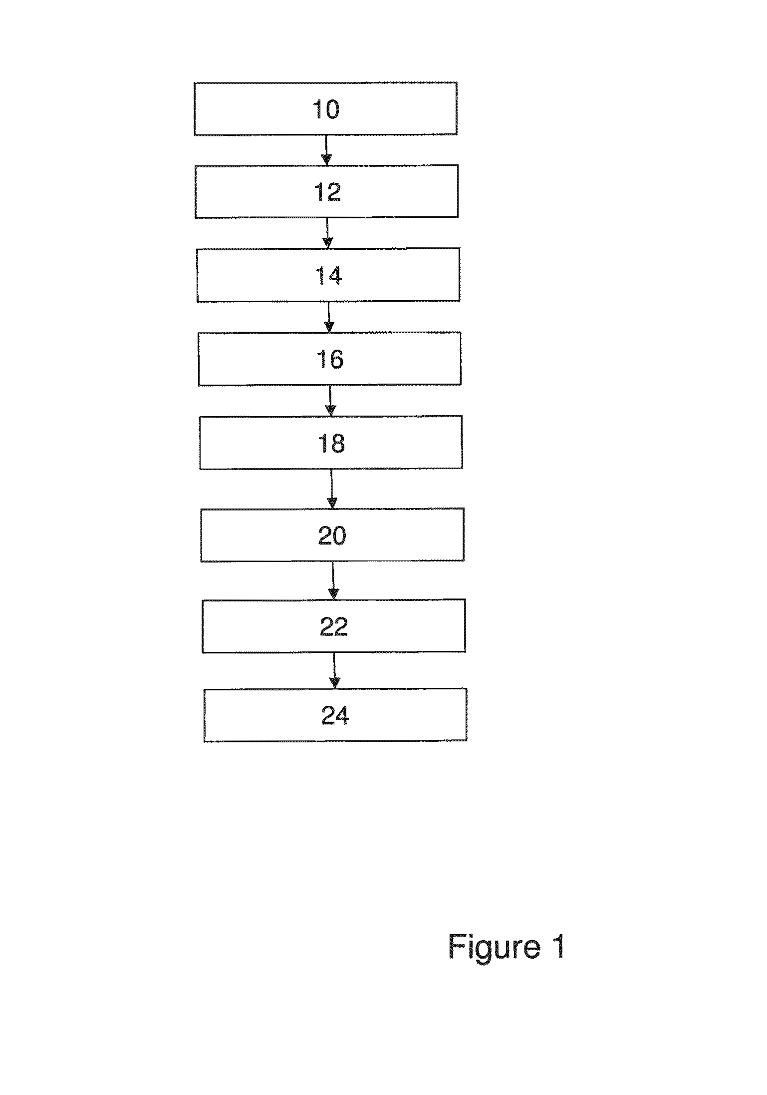
[0054]FIG. 1 shows a flow chart schematically representing a method of producing an acoustic field according to a first embodiment of the invention.

[0055]The method begins at step 10, in which in which a plurality of control points are defined. A control point is a point positioned in a space through which the acoustic field may propagate, at which the amplitude or phase of the acoustic field is to be controlled A control point is a marker at a particular location. The distance between adjacent control points should be sufficient to enable the sound waves of the acoustic field to phase shift from one of the control points to match the next control point. In some embodiments the separation distance may be equal to the wavelength of the sound waves of the acoustic field, for example a separation of 8.5 mm for a 40 kHz carrier wave. In some embodiments, the separation distance may be equal to half the wavelength of the sound waves of the acoustic field. In some embodiments the separati...


PUM


Abstract

A plurality of control points are defined having a known spatial relationship relative to an array of transducers. An amplitude is assigned to each control point. A matrix is produced containing elements which represent, for each of the control points, the effect that producing a modeled acoustic field having the assigned amplitude with a particular phase at the control point has on the consequential amplitude and phase of the modeled acoustic field at the other control points. Eigenvectors of the matrix are determined, each eigenvector representing a set of phases and relative amplitudes of the modeled acoustic field at the control points. One of the sets is selected and the transducer array is operated to cause one or more of the transducers to output an acoustic wave each having an initial amplitude and phase such that the phases and amplitudes of the resultant acoustic field at the control points correspond to the phases and relative amplitudes of the selected set.

Description

BACKGROUND[0001]It is known to use a continuous distribution of sound energy, which will be referred to herein as an “acoustic field”, for a range of applications, including haptic feedback.[0002]It is known to control an acoustic field by defining one or more control points in a space within which the acoustic field may exist. Each control point is assigned an amplitude value equating to a desired amplitude of the acoustic field at the control point. Transducers are then controlled to create an acoustic field exhibiting the desired amplitude at each of the control points.[0003]However, known systems for producing an acoustic field using control points suffer from limitations when a large number of control points are used.SUMMARY OF INVENTION[0004]According to a first aspect of the present invention there is provided a method of producing an acoustic field using an array of transducers having known relative positions and orientations, the method comprising:[0005]defining a plurality...

Claims


Application Information

Patent Timeline
IPC IPC(8): G01S7/52G01S15/36G01S7/539G01S15/87
CPCG01S7/52004G01S15/876G01S2007/52007G01S7/52003G01S7/539G01S15/36H04S7/30G06F3/016G06F3/017G03H2001/0061G06F3/043G10K15/00G06F3/015G06F3/04815
Inventor CARTER, THOMAS ANDREWLONG, BENJAMIN JOHN OLIVERSUBRAMANIAN, SRIRAM
Owner ULTRAHAPTICS IP LTD
Why Eureka
Try Eureka