
Low-carbon power machine

A power machine and motor technology, applied in the field of power machinery, can solve the problems of low conversion efficiency, environmental pollution, large volume, etc., and achieve the effect of high power output efficiency and zero emission

Inactive Publication Date: 2011-02-16
姜树早
View PDF0 Cites 1 Cited by
  • Summary
  • Abstract
  • Description
  • Claims
  • Application Information

AI Technical Summary

Problems solved by technology

[0002] There are multiple engines in the prior art, such as piston engines with gasoline, diesel oil, natural gas, liquefied gas, etc. as energy sources, which convert chemical energy into mechanical energy, but the conversion efficiency is low and pollutes the environment; Hydro turbines and engines powered by solar energy convert water energy, wind energy, and solar energy into mechanical energy. Although they are non-polluting, they are large in size, which is not conducive to miniaturization and mobile equipment.

Method used


Image

  • Low-carbon power machine
  • Low-carbon power machine
  • Low-carbon power machine

Examples


Embodiment Construction

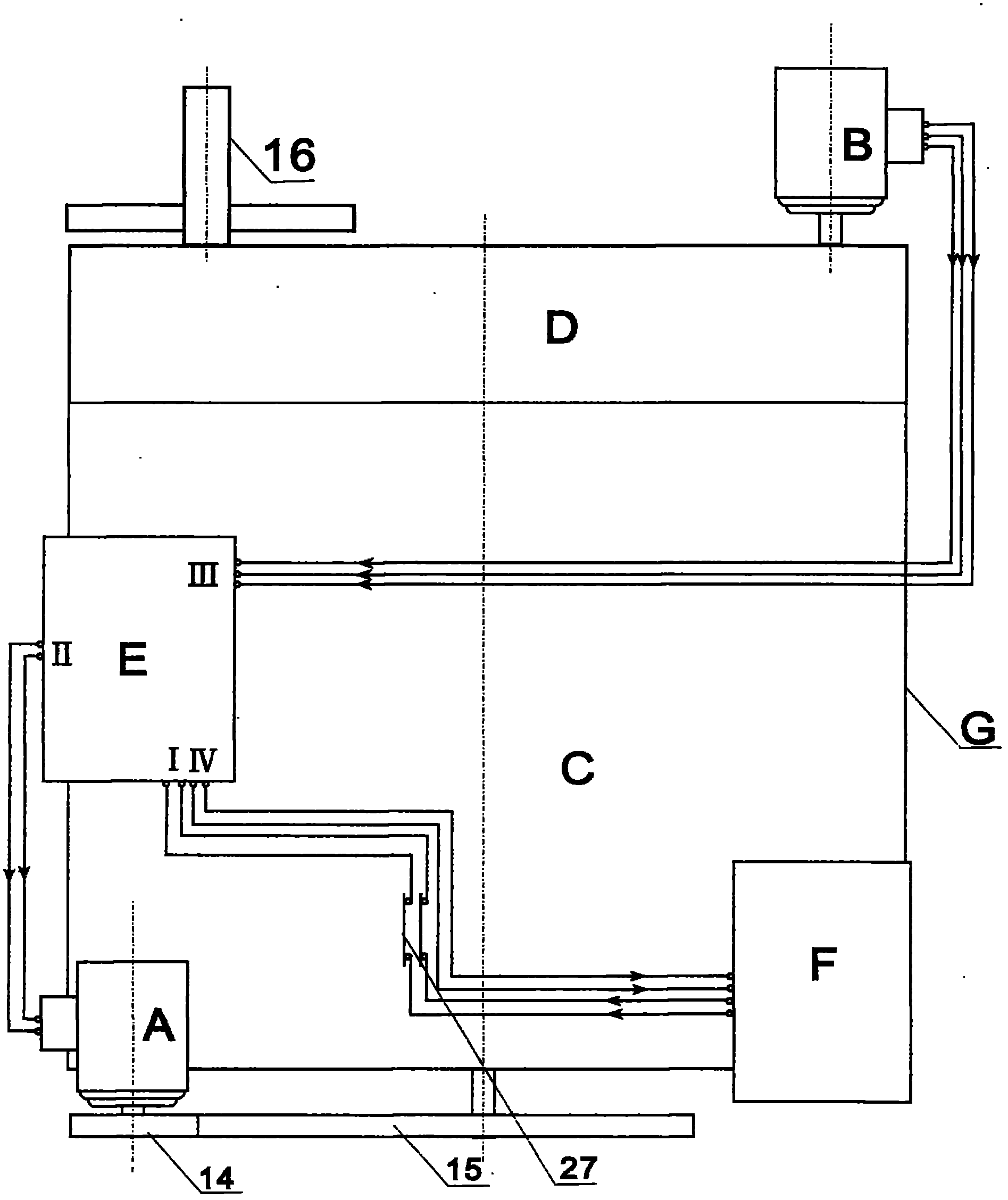
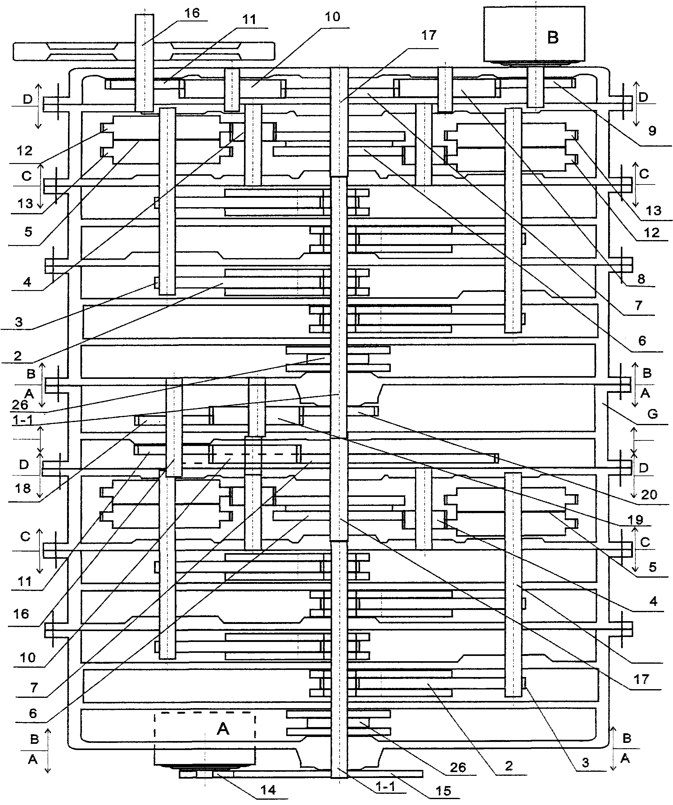
[0022] see figure 1 , figure 2 , Figure 12 , a low-carbon power machine, which is composed of a combination of 1 box or N boxes, and the box (G) is equipped with a motor (A), a generator (B), a centralized controller (E), and a battery pack (F). It includes three parts: booster transmission mechanism device (C), centralized controller device (E), output speed fine-tuning device (D).

[0023] This embodiment is an example of a low-carbon power machine with two cabinets combined. In the accompanying drawings of the present embodiment, the dimensions transmitted between the belt pulley and the gear are all drawn according to the scale of the design drawings of the present invention.

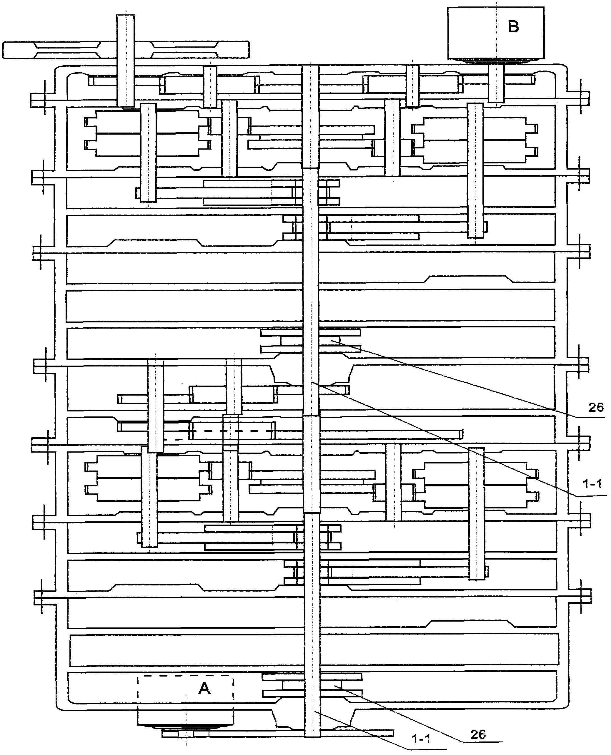
[0024] see figure 1 , figure 2 , image 3 , Figure 4 , Figure 5 , Figure 11 , the pulley (14) on the shaft of the motor (A) and the power transmission of the input shaft end [crankshaft (1-1)] pulley (15) of the power-increasing transmission mechanism device (C), and the small pulley...


PUM


Abstract

The invention discloses a low-carbon power machine which is formed by combining a box body or N box bodies. A motor, a generator, a centralized controller and a battery pack are installed on the box body; the motor is in power connection with the input shaft end of a boosting transfer mechanism device; the generator is in power connection with the output shaft end of an output rotating speed fine tuning device; the battery pack is electrically connected with the input end of a centralized controller device; the generator is electrically connected with the input end of the centralized controller device; the output end of the centralized controller device is electrically connected with the motor; the output end of the centralized controller device is electrically connected with a battery pack charger; the centralized controller device is provided with an inverter, a frequency converter, a transformer, a charger, a component and a circuit board; and the boosting transfer mechanism device is provided with two groups of crank shafts which are symmetrical right and left and are overlapped in the upper layer and the lower layer, connecting rods, levers and clutches which are organically combined. The invention has the advantages of high power output efficiency, low carbon, energy saving, zero emission and beneficial small, medium, low-power and high-power development and production.

Description

technical field [0001] The invention relates to a power machine, a low-carbon power machine capable of outputting relatively large mechanical energy. Background technique [0002] There are multiple engines in the prior art, such as piston engines with gasoline, diesel oil, natural gas, liquefied gas, etc. as energy sources, which convert chemical energy into mechanical energy, but the conversion efficiency is low and pollutes the environment; Hydro turbines and engines using solar energy as energy sources convert water energy, wind energy, and solar energy into mechanical energy. Although they are non-polluting, they have large volumes, which are not conducive to miniaturization and mobile equipment. Contents of the invention [0003] The purpose of the present invention is to overcome the defects of the prior art, and provide a low-carbon power machine that is converted into mechanical energy through the organic combination of physical principles and control principles, ...

Claims


Application Information

Patent Timeline
Patent Type & Authority Applications(China)
IPC IPC(8): H02K53/00H02J7/14H02K7/10
CPCY02T10/92
Inventor 姜树早
Owner 姜树早
Learn More