Fuel engine with swash plate shaft

A fuel engine, swash plate shaft technology, applied in the direction of machine/engine, mechanical equipment, etc., can solve the problems of low power output efficiency, large volume, heavy and other problems, and achieve the effect of high power output efficiency, light weight and small volume

Inactive Publication Date: 2015-09-23
周海云
View PDF5 Cites 1 Cited by
  • Summary
  • Abstract
  • Description
  • Claims
  • Application Information

AI Technical Summary

Problems solved by technology

This kind of fuel engine using a crankshaft structure has the following defects: low power output efficiency; un

Method used


Image

  • Fuel engine with swash plate shaft
  • Fuel engine with swash plate shaft
  • Fuel engine with swash plate shaft

Examples


Embodiment Construction

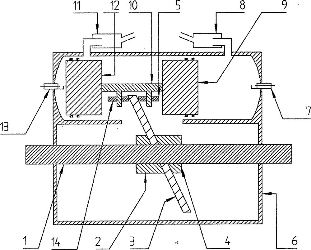
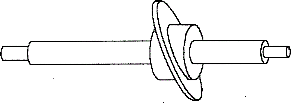
[0012] Such as figure 1 As shown, the swash plate reinforced clamp block 2, swash plate 3, and swash plate reinforced clamp block 4 are installed and fixed on the main shaft 1, and jointly constitute the swash plate shaft; The two combustion chambers are respectively equipped with spark plug 7 and spark plug 13; piston 9 and piston 12 are connected by connecting rod 10; connecting rod 10 is axially parallel to main shaft 1; bearing 5 and bearing 14 are installed on connecting rod 10; bearing 5 and A swash plate 3 is inserted in the middle of the bearing 14, and the swash plate 3 and the bearing keep a tight fit and can slide well.

[0013] The swash plate shaft fuel engine works in a two-stroke manner. When the swash plate shaft fuel engine works, the combustion chamber where the piston 9 is located and the combustion chamber where the piston 12 is located work alternately. When the combustion chamber where the piston 12 is located works, the spark plug 13 ignites, ignites th...


PUM


Abstract

The invention relates to a fuel engine with a swash plate shaft. The fuel engine comprises a housing, pistons, a connecting rod, bearings, a main shaft, a swash plate, swash plate strengthening clamping blocks, spark plugs and exhaust pipes. One swash plate strengthening clamping block, the swash plate and the other swash plate strengthening clamping block are fixedly installed on the main shaft in order and form a rotatable swash plate shaft; the pistons fixed on two ends of the connecting rod and the end portions of the housing form two combustion chambers, and the spark plugs are installed in the combustion chambers; and the connecting rod is provided with two bearings, the swash plate is inserted between the two bearings, and the swash plate is in close fit with the bearings and can slide well. The fuel engine with the swash plate shaft is high in power output efficiency, under the condition of certain discharge capacity, the fuel engine is small in size and light in weight, and the fuel engine can be applied to aircrafts.

Description

technical field [0001] The invention relates to an engine, in particular to a swash plate shaft fuel engine which can be used on multi-axis aircraft, model airplane helicopters and unmanned aerial vehicles. technical background [0002] At present, the motors used in multi-axis aircraft, aircraft model helicopters, and drones are divided into two types: brushless motors and gas engines. The fuel engine used on the man-machine is a single-cylinder / multi-cylinder fuel engine composed of the housing, piston and output crankshaft in an "L" shape. Or the rotors of a drone spinning. The fuel engine using the crankshaft structure has the following defects: the power output efficiency is low; under the condition of a certain displacement, the volume is large and heavy; so it is not conducive to the use of aircraft. Contents of the invention [0003] The technical problem solved by the present invention is to provide a fuel engine that can overcome the above-mentioned problems, h...

Claims


Application Information

Patent Timeline
IPC IPC(8): F02B75/32F02B75/28F02B75/34
Inventor 周海云
Owner 周海云
Why Eureka
Try Eureka