
Automatic adjustment device in novel engine energy-storage flywheel

An energy storage flywheel and automatic adjustment technology, which is applied in the direction of flywheel, vibration suppression adjustment, mechanical equipment, etc., can solve the problems of easy wear, deflection of flywheel center of gravity affecting engine work, and inconvenient and quick handling and assembly.

Inactive Publication Date: 2021-05-18
HUNAN UNIV OF TECH
View PDF0 Cites 1 Cited by
  • Summary
  • Abstract
  • Description
  • Claims
  • Application Information

AI Technical Summary

Problems solved by technology

[0005] Aiming at the deficiencies of the prior art, the present invention provides a new type of automatic adjustment device inside the energy storage flywheel of the engine, which can facilitate the rotation of the flywheel, provide higher inertial energy storage, have a longer service life, reduce wear and facilitate maintenance It solves the problem that the traditional equipment handling and assembly are not convenient enough, easy to wear and tear, resulting in the deflection of the center of gravity of the flywheel and affecting the normal engine work.

Method used


Image

  • Automatic adjustment device in novel engine energy-storage flywheel
  • Automatic adjustment device in novel engine energy-storage flywheel
  • Automatic adjustment device in novel engine energy-storage flywheel

Examples


Embodiment Construction

[0023] The following will clearly and completely describe the technical solutions in the embodiments of the present invention with reference to the accompanying drawings in the embodiments of the present invention. Obviously, the described embodiments are only some, not all, embodiments of the present invention. Based on the embodiments of the present invention, other embodiments obtained by persons of ordinary skill in the art without making creative efforts all belong to the protection scope of the present invention.

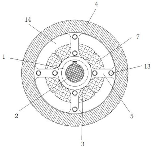
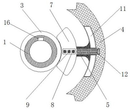
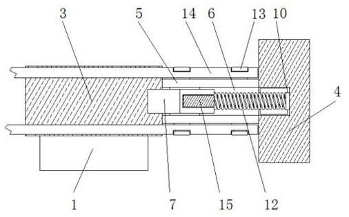
[0024] see Figure 1-3 , a new type of automatic adjustment device inside the engine energy storage flywheel, including a fixed ring 1, the inside of the fixed ring 1 is fixedly connected with a power rod 2, the outer wall of the fixed ring 1 is surrounded and fixedly connected with a snap ring 3, and the snap ring 3 The outer wall of the outer wall is surrounded by a load-bearing ring 4, and the inner wall of the load-bearing ring 4 is fixedly connected with ...


PUM


Abstract

The invention discloses an automatic adjustment device in a novel engine energy-storage flywheel. The automatic adjustment device comprises a fixed ring, wherein a power rod is fixedly connected to the interior of the fixed ring; a clamping ring is fixedly connected to the outer wall of the fixed ring in a surrounding form; a weight-bearing ring is arranged on the outer wall of the clamping ring in a surrounding form; the inner wall of the weight-bearing ring is mutually and fixedly connected to the outer wall of the clamping ring through connecting rods; through grooves are formed in the connecting rods in a penetrating manner; and counter weights are arranged in the through grooves. According to the automatic adjustment device disclosed by the invention, the counter weights are away from the weight-bearing ring and are moved toward the position of the clamping ring; magnet blocks in the counter weights mutually attract the clamping ring, and the clamping ring is fixed, so that the whole gravity of the device can be distributed more evenly; and the power rod has lower inertia at beginning of rotation, and the device has the advantages that convenience is provided for the flywheel to rotate, higher inertia is provided, the device has longer service life, abrasion is weakened, and the device is convenient to repair.

Description

technical field [0001] The invention relates to the technical field of engine flywheel machinery, in particular to an automatic adjustment device inside a novel engine energy storage flywheel. Background technique [0002] In the engine system, the engine flywheel is a disc with a large moment of inertia, which acts as an energy storage. The larger the moment of inertia, the more energy storage. The flywheel is installed on the flange at the rear end of the engine crankshaft. Its main function is The energy is stored, so that the uneven rotation of the crankshaft during operation is alleviated. [0003] The structure of the flywheel in the traditional engine system is usually a single cast iron component, and its mass is mostly distributed on the outer edge of the flywheel, resulting in a large moment of inertia and a large amount of energy storage, but a large moment of inertia will make it difficult for the power machine to start. Therefore, the traditional one-piece flyw...

Claims


Application Information

Patent Timeline
IPC IPC(8): F16F15/31F16F15/14
CPCF16F15/1421F16F15/31Y02E60/16
Inventor 陈一
Owner HUNAN UNIV OF TECH
Learn More