Coaxial four-reflector ultra-low distortion optical system

An optical system, coaxial technology, applied in the field of aerospace optical remote sensors, can solve the problems of mirror processing, detection and adjustment cannot be used, optical design tangential meridian distortion is difficult to control, and mirror processing is difficult, etc. Accurate temperature and pointing control, eliminating stray light outside the field of view, and high structural stability

Active Publication Date: 2013-01-09
BEIJING RES INST OF SPATIAL MECHANICAL & ELECTRICAL TECH
View PDF5 Cites 27 Cited by
  • Summary
  • Abstract
  • Description
  • Claims
  • Application Information

AI Technical Summary

Problems solved by technology

Among them, the processing of the mirror of the off-axis reflective system is extremely difficult, and traditional methods cannot be used for mirror processing, testing, and adjustment. It is difficult to control the tangential meridional distortion of the optical design, the system engineering is difficult, and the temperature control accuracy is difficult to guarantee. Optics especially unsuitable for agile stereo mapping cameras
Although the coaxial reflective three-mirror astigmatism elimination system has good system engineering and is easy to achieve high-precision temperature control, it cannot achieve a large field of view and the system distortion is difficult to eliminate
The optical system distortion of the three-dimensional surveying and mapping cameras that have been successfully operated in orbit and adopt the coaxial reflective three-mirror astigmatism elimination structure is greater than one percent. Difficult to meet the development needs of future surveying and mapping cameras

Method used


Image

  • Coaxial four-reflector ultra-low distortion optical system
  • Coaxial four-reflector ultra-low distortion optical system
  • Coaxial four-reflector ultra-low distortion optical system

Examples


Embodiment Construction

[0025] Below in conjunction with accompanying drawing and specific embodiment the present invention is described in further detail:

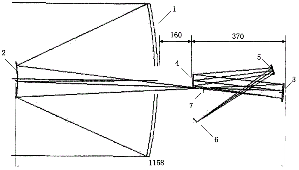
[0026] In the embodiment of the present invention, the working spectrum is 0.5-0.9 μm, the entrance pupil diameter is 625 mm, the focal length of the optical system is 10 m, the full field of view is 1.5°, and the total length of the system is 1158 mm.

[0027] Such as figure 1 Shown is a structural diagram of the optical system of the present invention, from which it can be seen that the optical system of the present invention includes: a primary mirror 1, a secondary mirror 2, a third mirror 3, a fourth mirror 4, a plane mirror 5 and a receiving image surface 6. The optical axes of the primary mirror 1, the secondary mirror 2, the third mirror 3, the fourth mirror 4 and the plane mirror 5 are on the same straight line and are coaxial. The primary mirror 1 and the secondary mirror 2 constitute a classic R-C system, and form a primary real imag...


PUM


Abstract

The invention relates to a coaxial four-reflector ultra-low distortion optical system, which comprises a primary mirror, a secondary mirror, a third mirror, a fourth mirror, a plane mirror and a receiving image plane, wherein optical axes of the primary mirror, the secondary mirror, the third mirror, the fourth mirror and the plane mirror are in a same straight line; the plane mirror is located between the third mirror and the fourth mirror; the primary mirror and the secondary mirror constitute a classical R-C system and form a primary real image, which continues imaging when passing through the third mirror and the fourth mirror and deflects to the receiving image plane through the plane mirror; the primary mirror, the secondary mirror and the third mirror constitute a coaxial TMA system and assume most of focal power; the fourth mirror assumes smaller part of focal power, accounting for 10-20% of the total focal power, in the imaging of the optical system; and an aperture diaphragm of the optical system is located on the primary mirror and the fourth mirror is placed at an exit pupil of the system. The optical system of the invention can be used to realize high image quality, low distortion and high stability and greatly reduce the processing difficulty of a large-aperture primary mirror and is suitable for high-precision satellite-borne stereo mapping cameras.

Description

technical field [0001] The invention belongs to the technical field of aerospace optical remote sensors, and relates to an ultra-low distortion high-precision three-dimensional surveying and mapping imaging optical system suitable for satellite-borne space to the ground, in particular to a coaxial four-mirror ultra-low distortion optical system. Background technique [0002] With the continuous development of space optical remote sensing technology, the requirements for the optical system of surveying and mapping cameras are becoming increasingly stringent. [0003] The main task of surveying and mapping satellites is to carry imaging sensors that meet the requirements of stereo photography to perform stereo photography on the earth's surface, obtain multi-dimensional image data of ground objects, use surveying and mapping processing technology to process image data, and accurately measure landforms, shape, size, attributes and Spatial position information, however, the dist...

Claims


Application Information

Patent Timeline
Patent Type & Authority Applications(China)
IPC IPC(8): G02B17/06G02B5/10G02B1/10G01C11/02
Inventor 苏云杨秉新张鹏斌汤天瑾周峰
Owner BEIJING RES INST OF SPATIAL MECHANICAL & ELECTRICAL TECH
Why Eureka
Try Eureka