Connector for multiple core optical fiber

a fiber optic connector and fiber optic technology, applied in the field of fiber optic connectors, can solve the problems of degrading communication performance in one or more cores, difficult pre-cutting of the internal cavity of the plug housing, and increasing costs, so as to increase or decrease the force between mated connectors, increase the cost, and degrade communication performance

Inactive Publication Date: 2016-06-23
COMMSCOPE INC
View PDF4 Cites 2 Cited by
  • Summary
  • Abstract
  • Description
  • Claims
  • Application Information

AI Technical Summary

Benefits of technology

The present invention provides a low cost and reliable fiber optic plug that can hold multiple cores in proper alignment with a mating connector. This plug design allows for a spring to control the mating force between connectors, while also allowing for longitudinal movement of the ferrule relative to the housing. This reduced the likelihood of failure and increased reliability in the optical communication performance.

Problems solved by technology

It is appreciated that precision molding of the internal cavity of the plug housing is difficult and increases the costs.
Further, the plastic portions of the housing can be subject to abrasion and may over time expand to develop play in the nesting between the external geometry of the ferrule holder and the internal geometry of the plug housing, which could lead to degraded communication performance in one or more cores.
An interference fit or bonded fit between the ferrule holder and housing can increase or decrease the force between mated connectors, especially when manufacturing tolerances along the axis of the connector system vary.

Method used


Image

  • Connector for multiple core optical fiber
  • Connector for multiple core optical fiber
  • Connector for multiple core optical fiber

Examples


first embodiment

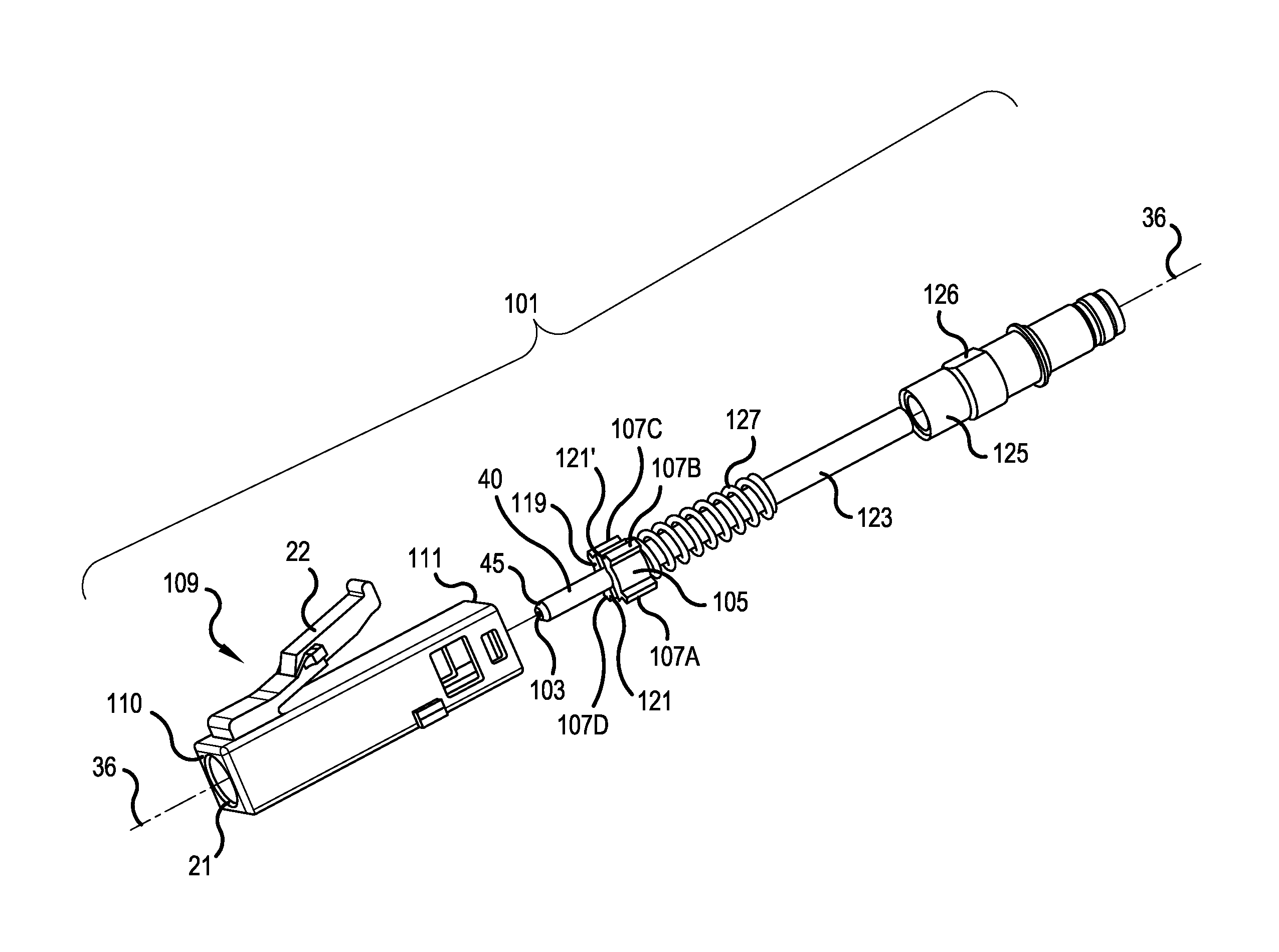
[0053]FIG. 7 is an exploded, perspective view of a first multi-core fiber (MCF) connector 101, in accordance with the present invention. Structures, which are the same or similar to the prior art depicted in FIGS. 1-3 have been labeled by a same reference numeral. The first MCF fiber connector 101 includes a ferrule 40, which is cylindrical in shape. A multi-core fiber 103 is secured within a central bore of the ferrule 40, e.g., by epoxy. A ferrule barrel 105 surrounds at least a portion of the ferrule 40, and may be attached to the ferrule 40 by epoxy or by a press fit.

[0054]The ferrule barrel 105 includes at least one spline 107 extending away from an outer peripheral surface of the ferrule barrel 105. In a preferred embodiment, the at least one spline 107 includes four splines 107A, 107B, 107C and 107D, each extending away from the outer peripheral surface of the ferrule barrel 105, and the four splines 107A, 107B, 107C and 107D are equally spaced around the peripheral surface o...

second embodiment

[0062]FIG. 10 is an exploded, perspective view of a second MCF connector 201, in accordance with the present invention. Structures, which are the same or similar to the prior art or earlier embodiments, have been labeled by a same reference numeral. The second MCF fiber connector 201 includes a ferrule 40, which is cylindrical in shape. A multi-core fiber 103 is secured within a central bore of the ferrule 40, e.g., by epoxy. A ferrule barrel 205 surrounds at least a portion of the ferrule 40, and may be attached to the ferrule 40 by epoxy or by a press fit.

[0063]The ferrule barrel 205 includes at least one spline 207 extending away from an outer peripheral surface of the ferrule barrel 205. In a preferred embodiment, the at least one spline 207 includes four splines 207A, 207B, 207C and 207D, each extending away from the outer peripheral surface of the ferrule barrel 205, and the four splines 207A, 207B, 207C and 207D are equally spaced around the peripheral surface of the ferrule ...

third embodiment

[0071]FIG. 13 is an exploded, perspective view of a third multi-core fiber (MCF) connector 301, in accordance with the present invention. Structures, which are the same or similar to the prior art or earlier embodiments, have been labeled by a same reference numeral. The third MCF fiber connector 301 includes a ferrule 40, which is cylindrical in shape. A multi-core fiber 103 is secured within a central bore of the ferrule 40, e.g., by epoxy. A ferrule barrel 305 surrounds at least a portion of the ferrule 40, and may be attached to the ferrule 40 by epoxy or by a press fit.

[0072]The ferrule barrel 305 includes at least one spline 307 extending away from an outer peripheral surface of the ferrule barrel 305. In a preferred embodiment, the at least one spline 307 includes first and second splines 307A and 307B, each extending away from the outer peripheral surface of the ferrule barrel 305, and the first and second splines 307A and 307B are equally spaced around the peripheral surfac...


PUM


Abstract

A fiber optic plug, suitable for multi-core fiber (MCF), is structured to hold satellite cores of the MCF in a precise angular positions so as to attain suitable alignment with satellite cores of a mating connector. The plug includes features to permit a ferrule holding the MCF to move longitudinally relative to the connector's housing, so that a spring may control a mating force to an abutting ferrule of a mating connector. The ferrule may be held by ferrule barrel having splines projecting away from an outer peripheral surface. The splines may slide longitudinally within notches of the connector housing or a strength member attached to the connector housing. The notches and splines have a tight tolerance, so that the satellite cores remain in a desired, set angular position.

Description

[0001]This application is a continuation of application Ser. No. 14 / 303,551, filed Jun. 12, 2014, which claims the benefit of U.S. Provisional Application No. 61 / 834,796, filed Jun. 13, 2013, with the entire contents of the two prior applications being herein incorporated by reference.BACKGROUND OF THE INVENTION[0002]1. Field of the Invention[0003]The present invention relates to a fiber optic connector. More particularly, the present invention relates to a fiber optic connector, which enables precise alignment of the cores of a multi-core fiber end presented by the fiber optic connector relative to a feature of the connector envelope or a feature attached to the ferrule of the fiber optic connector, while enabling the ferrule to reciprocate longitudinally within the connector envelope.[0004]2. Description of the Related Art[0005]FIG. 1 shows an exploded view of a simplex connector, in the form of an LC connector 30, in accordance with the prior art. The LC connector 30 comprises th...

Claims


Application Information

Patent Timeline
Patent Type & Authority Applications(United States)
IPC IPC(8): G02B6/38
CPCG02B6/3885G02B6/3874G02B6/3871G02B6/3821G02B6/3882G02B6/3893
Inventor NIELSON, JEFFREY D.
Owner COMMSCOPE INC
Why Eureka
Try Eureka