Load lowering system

Inactive Publication Date: 2004-10-07
RICHEY WILLIAM H +1
View PDF28 Cites 2 Cited by
  • Summary
  • Abstract
  • Description
  • Claims
  • Application Information

AI Technical Summary

Benefits of technology

[0011] During assembly, the two friction rods and the glide rod are vertically aligned and mounted on the sides of a building. The two friction rods vary in diameter at different locations along their lengths which increases and decreases the forces applied by the friction collars as they descend on the friction rods. Each friction collar includes means for adjusting the amount of friction exerted on the friction rod so that the rate of descent of the friction collar on the friction rod may be controlled for a specific amount of load weight. The two friction collars are attached to an upper frame assembly located above the support platform upon which the load to be lowered is placed. During use, the diameters of the friction rods gradually increase or decrease so that the friction collars are used to control the descent of the upper frame assembly from a stored position located above the escape opening to the escape opening as well as assist in control of the descent of the support platform from the escape opening to the ground. The friction rods are also used secondarily to stabilize the support platform as it descends from the escape opening to the ground.

Problems solved by technology

One drawback with such systems is that the movement of the carriage is dependent upon a constant supply of electricity to operate the motor.
Another drawback with such systems is that they are relatively complex and use an electric motor and switches that require connection to the building electrical circuits.

Method used


Image

  • Load lowering system
  • Load lowering system
  • Load lowering system

Examples


Embodiment Construction

)

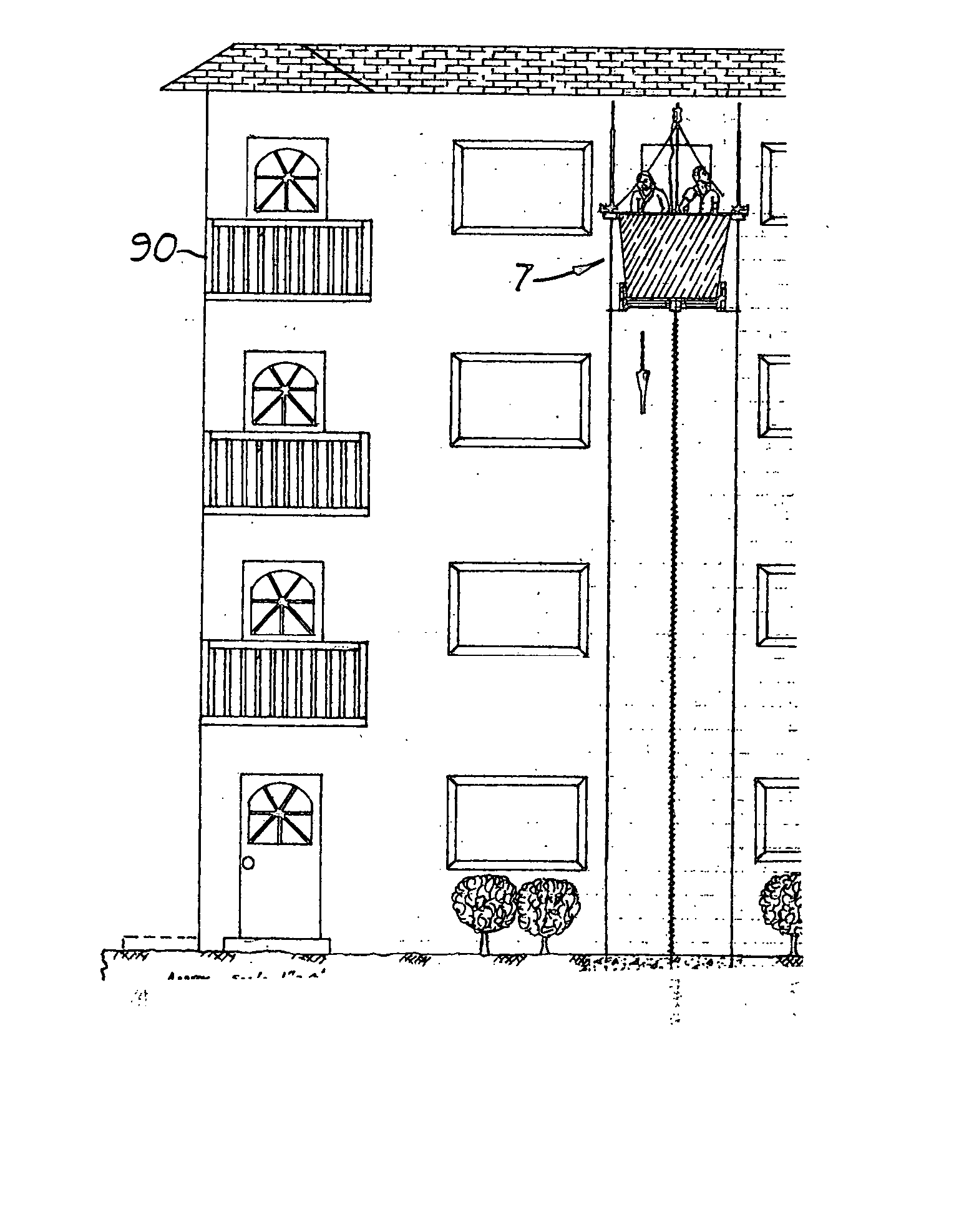
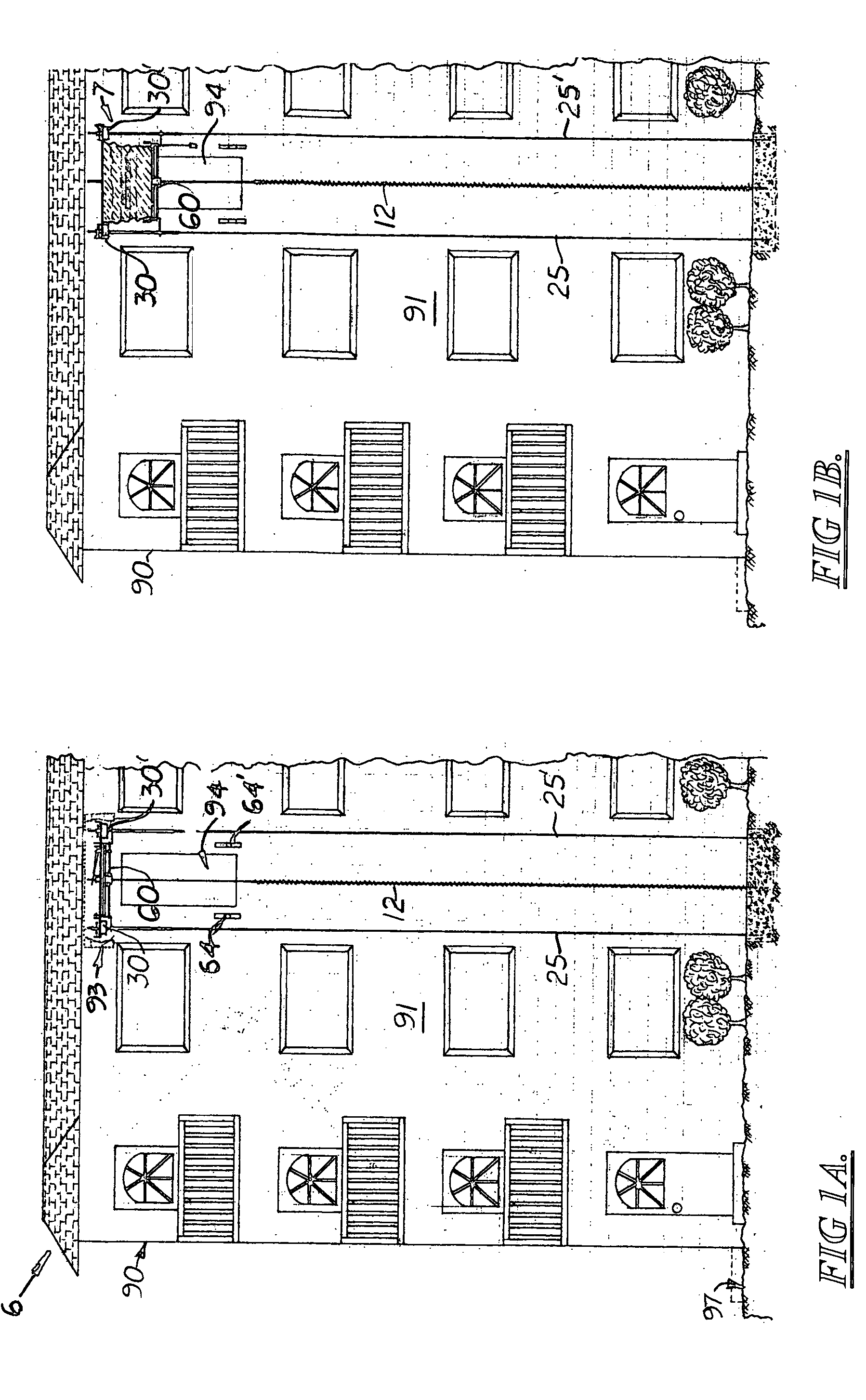
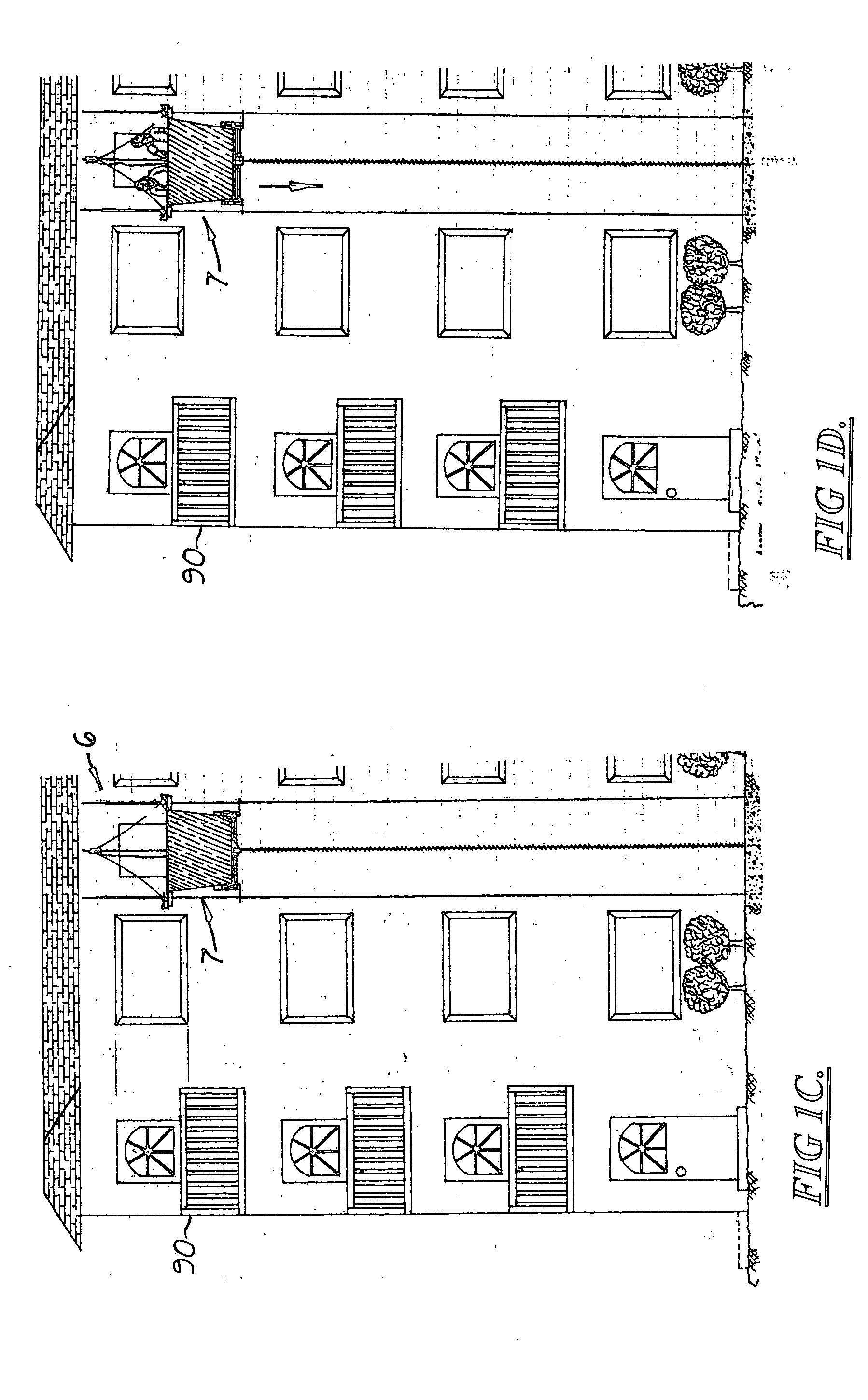
[0031] Shown in the 1A-1J is a system 6 for mechanically lowering a load from an elevated position, to a lower position in a relatively slow and controlled manner. The system 6, which is specifically designed not to require electricity, includes a load carrying carriage 7 that is initially stored in an elevated stored position 93 located above an escape opening 94 formed on the wall 91 of a building 90. When an emergency exists that requires a user located in the upper floor of a building 90 to quickly leave the building 90, an escape mechanism is activated which causes the carriage 7 to automatically descend from an elevated position 93 located on the wall 91 to the escape opening 94. The user then exits the building through the escape opening 94 and enters the carriage 7. The carriage 7 is then released from the escape opening 94, and slowly descends to the ground 97 where the user departs. The carriage 7 may then be returned to the escape opening 94 to pick up additional users o...


PUM


Abstract

A system for mechanically lowering a load from an elevated position to a lower position in a relatively slow and controlled manner using only gravity and frictional forces. The system includes a vertically aligned glide rod, a glide collar that moves longitudinally over the glide rod, two vertically mounted friction rods mounted on opposite sides of the glide rod, a friction collar that moves longitudinally along each friction rod, and a support platform coupled to each friction collar and to the glide collar. The glide rod includes spiral vane along its entire length upon which the glide collar rides when a load is placed on the support platform, allowing the support platform to descend at a safe speed via gravity. The friction rod and collars are used to move the support platform from a stored position located above the elevated loading position to a lower position so that a load may be placed onto the support platform and to stabilize the support platform as it descends from the loading position to the ground.

Description

[0001] This is a continuation-in-part patent application based on the provisional patent application (Application No. 60 / 413,968) filed on Sep. 26, 2002 and the utility patent application (application Ser. No. 10 / 672,214) filed on Sep. 25, 2003 and now abandoned.[0002] 1. Field of the Invention[0003] This invention relates to systems used to lower a load from an elevated location to a lower location, and more particularly, for such systems that include a platform that moves in a slow, controlled manner.[0004] 2. Description of the Related Art[0005] Exterior mounted fire escape systems that allow residents in the building to escape during a fire or emergency situation in the building are well known. One type of system includes a motor-driven carriage that moves over a rail vertically mounted on the outside of the building. One drawback with such systems is that the movement of the carriage is dependent upon a constant supply of electricity to operate the motor. Another drawback with ...

Claims


Application Information

Patent Timeline
IPC IPC(8): B66B9/00
CPCB66B9/00
Inventor RICHEY, WILLIAM H.BOLDING, JOHN
Owner RICHEY WILLIAM H
Why Eureka
Try Eureka