Fuel pressure control system for an internal combustion engine

a technology of internal combustion engine and control system, which is applied in the direction of machine/engine, fuel supply apparatus, charge feed system, etc., can solve the problem of not being able to achieve an efficient method of regulating fuel pressure, and achieve the effect of increasing or decreasing the biasing for

Active Publication Date: 2015-06-11
SVMTECH
View PDF6 Cites 1 Cited by
  • Summary
  • Abstract
  • Description
  • Claims
  • Application Information

AI Technical Summary

Benefits of technology

[0004]A resilient diaphragm spring exerts a biasing force against the diaphragm. An adjustment screw engages the resilient diaphragm spring and adjusts the biasing force against the diaphragm. In one preferred embodiment, the diaphragm position adjusting means comprises a pneumatic pressure regulator disposed on the fuel regulator block for exerting positive or negative pressure on the diaphragm. In this preferred embodiment, the adjustment screw establishes a base operating position of the diaphragm within the fuel regulator block. In another preferred embodiment, the diaphragm position adjusting means comprises a motor disposed on the fuel regulator block. The motor has an output shaft mechanically coupled to a spring locator on the resilient diaphragm spring to increase or decrease the biasing force of the resilient diaphragm spring against the diaphragm.

Problems solved by technology

However, the fuel pressure regulators of the prior art do not allow for an efficient method of varying the regulated fuel pressure.

Method used


Image

  • Fuel pressure control system for an internal combustion engine
  • Fuel pressure control system for an internal combustion engine
  • Fuel pressure control system for an internal combustion engine

Examples


Embodiment Construction

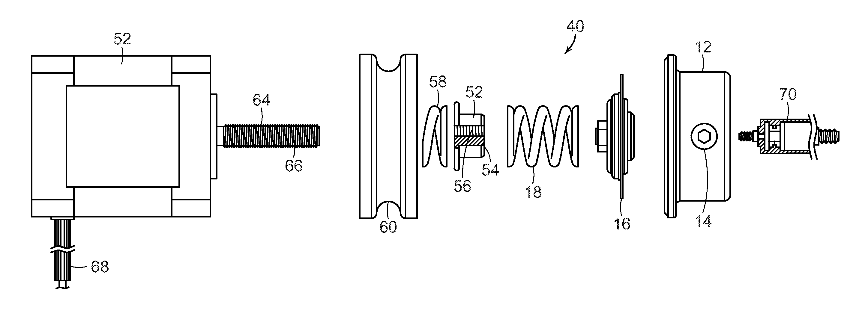
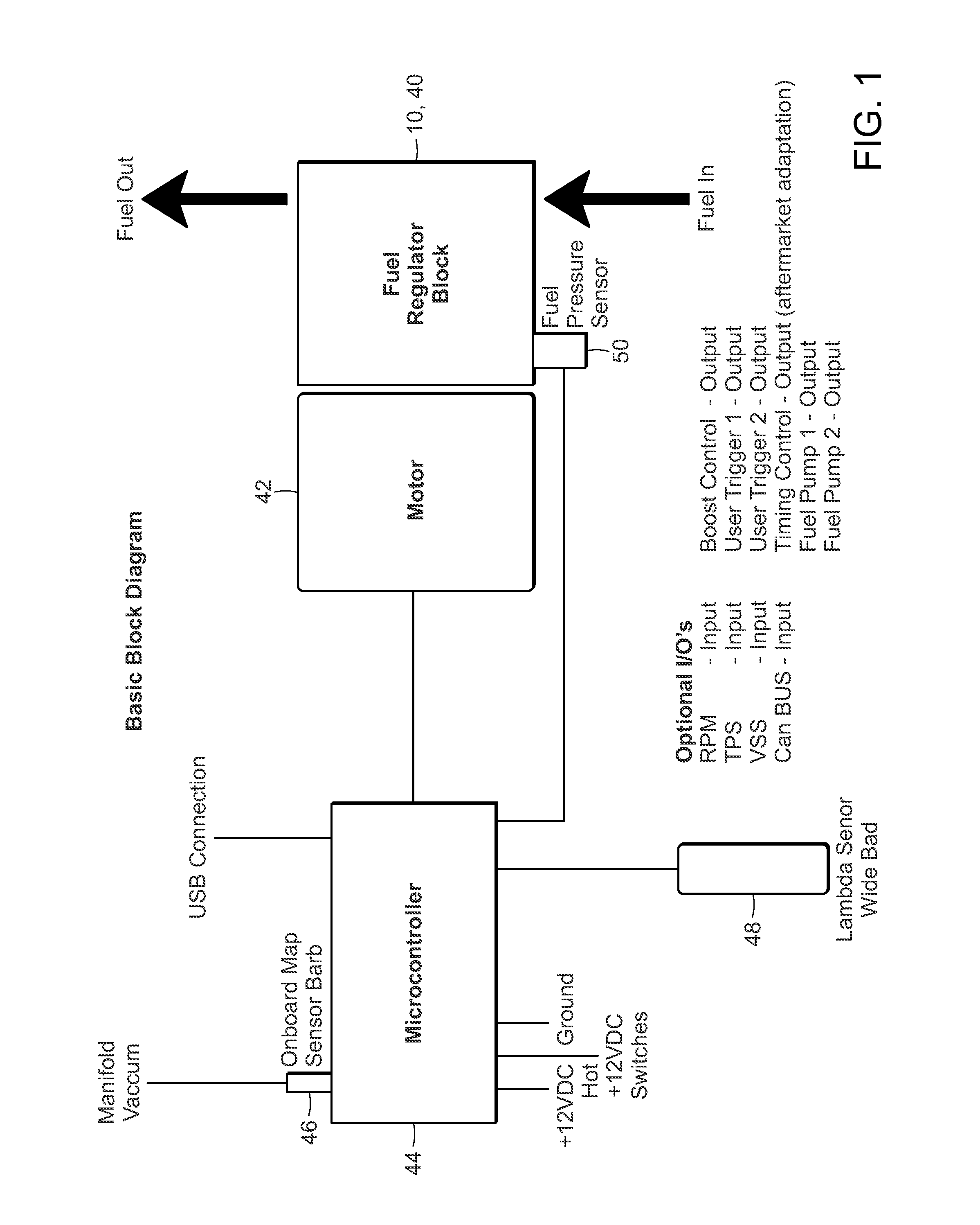
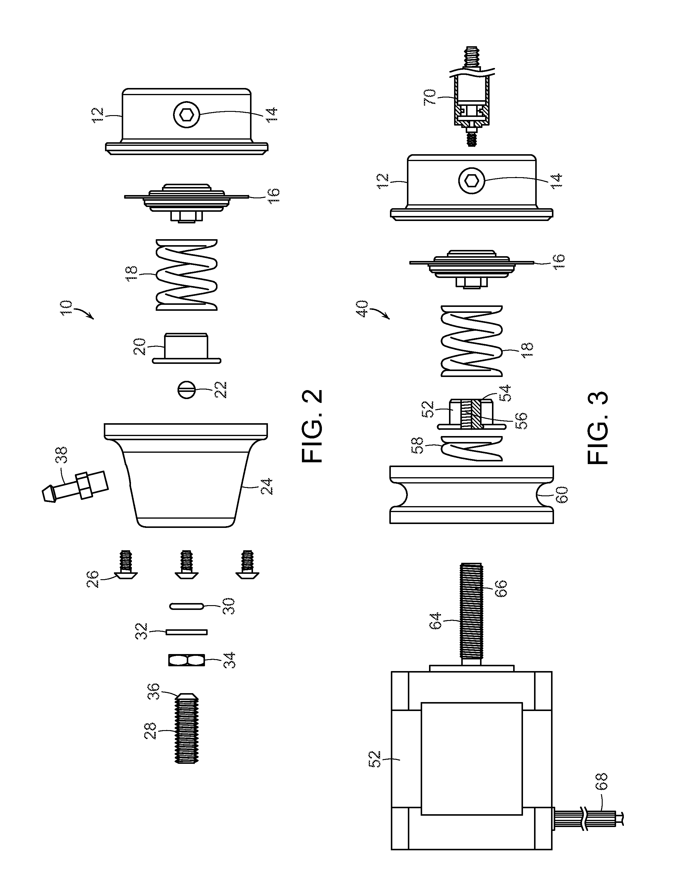
[0015]FIG. 1 illustrates a basic block diagram of an inventive fuel pressure regulator 10, 40, 72 installed in connection with an engine 42 and microcontroller 44. The regulator 40 is in line with a fuel inlet on the engine 42 and responsive to signals from the microcontroller 44. The microcontroller 44 senses various engine conditions, including but not limited to vacuum manifold, oxygen content, and fuel pressure, to mention a few. The microcontroller 44 has or is in electronic communication with a manifold vacuum sensor 46, a lambda or oxygen sensor 48, and a fuel pressure sensor 50. The lambda or oxygen sensor 48 is preferably a wide band zirconia sensor or similarly configured device. The lambda sensor 48 may also comprise a basic zirconium dioxide or zirconia sensor, or a titania made of titanium dioxide. The regulator is used by the system to control the pressure of the fuel entering the engine 42.

[0016]The microcontroller 44 preferably has a switchable lead such that voltage...


PUM


Abstract

A pneumatic fuel pressure regulator and a mechanical fuel pressure regulator are disclosed wherein the pneumatic fuel pressure regulator uses a mechanical adjustment screw to position a spring locator and spring force exerted on a diaphragm assembly controlling flow through a base fuel block. The mechanical fuel pressure regulator includes a stepper motor and a threaded drive shaft to control pressure exerted on a diaphragm assembly to regulate passage through a base fuel block. A dual stage system combines the pneumatic and mechanical regulators in a dual base unit having two ports separately controlled by the separate regulators.

Description

BACKGROUND OF THE INVENTION[0001]The present invention is generally directed to a fuel pressure regulator for a motor vehicle. More particularly, the present invention is directed to a programmable electronically controlled fuel pressure regulator.[0002]Fuel pressure regulators have been previously proposed. Spring based pressure regulators are known that use spring force to control a valve providing fluid communication to a return fuel line. However, the fuel pressure regulators of the prior art do not allow for an efficient method of varying the regulated fuel pressure. There is a need for a design that overcomes the shortcomings of the related art. The present invention fulfills these needs and provides other related advantages.SUMMARY OF THE INVENTION[0003]The present invention is directed to a fuel pressure control system for an internal combustion engine. The system comprises a fuel regulator block for a fuel injector. The fuel regulator block has an internal valve port and a ...

Claims


Application Information

Patent Timeline
Patent Type & Authority Applications(United States)
IPC IPC(8): F02M37/00F02D33/00
CPCF02D33/003F02M37/0029F02M21/0233F02M21/0239F02M21/0242
Inventor MONROS, SERGE V.
Owner SVMTECH
Why Eureka
Try Eureka