Anatomically-orientated and self-positioning transcatheter mitral valve

Active Publication Date: 2016-07-21
CEDARS SINAI MEDICAL CENT
View PDF3 Cites 72 Cited by
  • Summary
  • Abstract
  • Description
  • Claims
  • Application Information

AI Technical Summary

Benefits of technology

[0012]Accordingly, installation of the disclosed mitral prosthesis provides a unique opportunity to simultaneously implant a support structure or anchor for a prosthetic replacement for the adjacent aortic valve. This allows both ar

Problems solved by technology

However, typical mitral valve prosthesis are circular shaped and/or have flat surfaces that require rotational positioning, and therefore do not automatically conform to the natural geometry of the mitral valve opening.
This departure from the nature shape and/or lack of automatic conformity to th

Method used


Image

  • Anatomically-orientated and self-positioning transcatheter mitral valve
  • Anatomically-orientated and self-positioning transcatheter mitral valve
  • Anatomically-orientated and self-positioning transcatheter mitral valve

Examples


example 1

Surgical Procedure

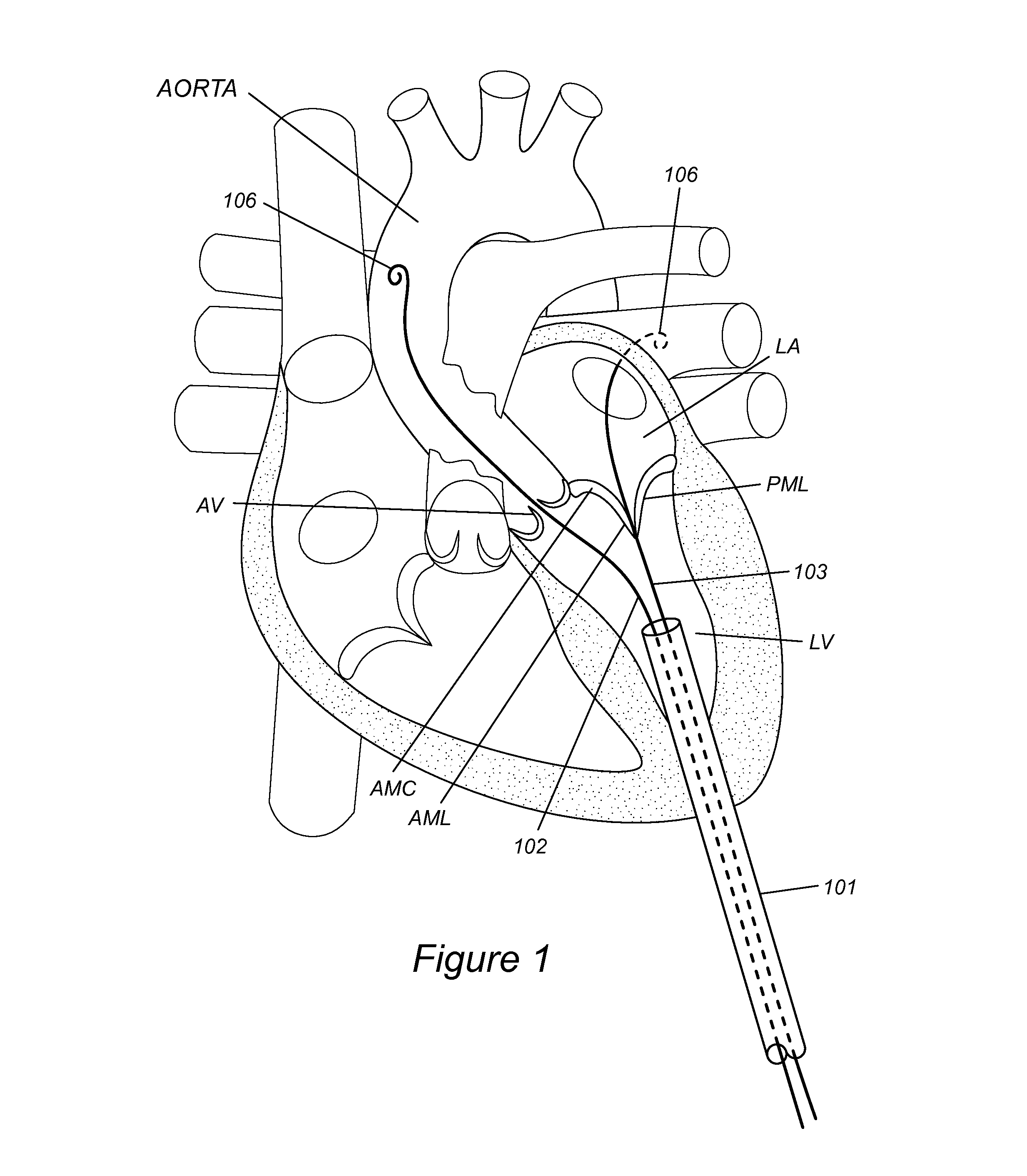
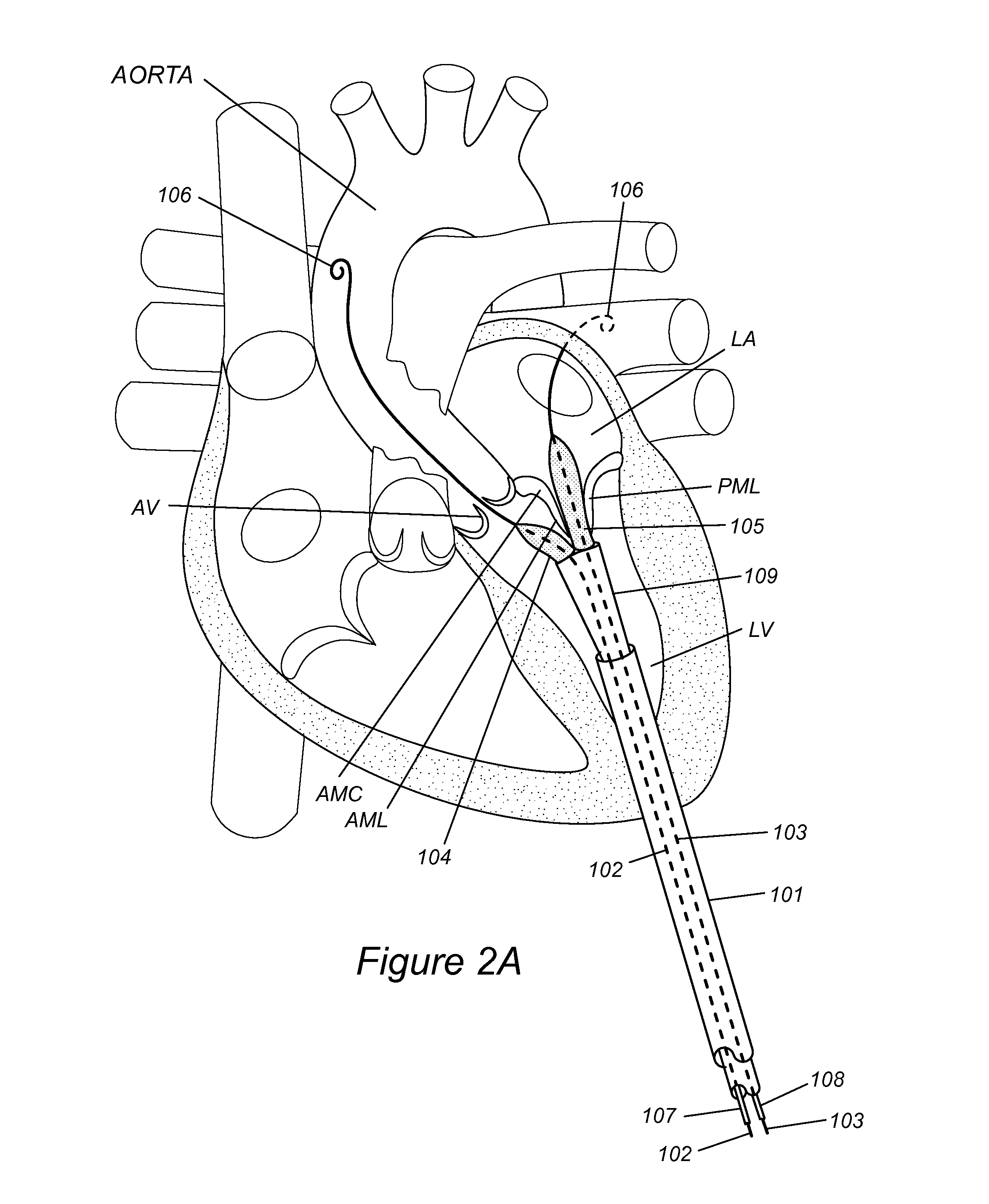
[0046]After induction of anesthesia, and sterile preparation, an incision is performed at the 5th intercostal space in the mid-clavicular line, cutting the intercostal muscles, and entering the left pleural cavity. Next, the pericardium over the left ventricular apex is opened, and four pledgeted sutures are placed at the site of entry. Next an 18 gauge needle and 0.035″ regular J-wire is inserted and advanced through the aortic valve. The needle is withdrawn and a 7 Fr sheath is used to cross the aortic valve over the wire and used to exchange out for a stiffer 0.035″ wire (Amplatzer Extra Stiff J-wire or equivalent). The 24 Fr sheath is inserted into the left ventricle over this wire. The subject is heparinized with an activated clotting time (ACT) over 250 sec.

[0047]A 0.035″ regular J-wire is inserted with a 6 Fr JR4 catheter and advanced through the apical sheath alongside the first wire and from the left ventricle, across the mitral valve and into the right up...


PUM


Abstract

Described herein is a mitral valve and systems and methods for implanting the same. The mitral valve device is designed to easily orient to and conform to the mitral orifice natural morphology. This mitral valve system may be implanted using a system of 2 guide wires that facilitate orientation of the flat portion of the stent properly with the flat portion of the mitral valve that is adjacent to the aortic valve. Additionally, the disclosed valve may have multiple mounds distributed across the outer surface of the valve/stent complex so as to prevent or reduce paravalvular leak after implantation.

Description

FIELD OF INVENTION[0001]The present invention is directed to devices, systems and methods for replacing the diseased mitral valve in a subject in need thereof.BACKGROUND OF THE INVENTION[0002]All publications cited herein are incorporated by reference in their entirety to the same extent as if each individual publication or patent application was specifically and individually indicated to be incorporated by reference. The following description includes information that may be useful in understanding the present invention. It is not an admission that any of the information provided herein is prior art or relevant to the presently claimed invention, or that any publication specifically or implicitly referenced is prior art.[0003]The presently available prosthesis for transcatheter mitral valve replacement (TMVR) are not designed to accommodate the unique anatomy of the mitral valve. Therefore, the outcomes of TMVR frequently are not favorable. For instance, incidents of paravalvular r...

Claims


Application Information

Patent Timeline
IPC IPC(8): A61F2/24
CPCA61F2/2412A61F2/2433A61F2/2418A61F2250/0003A61F2230/0034A61F2220/0016A61F2250/0067A61F2/2436A61F2250/0063A61F2250/006
Inventor AL-JILAIHAWI, HASANIANMAKKAR, RAJENDRA
Owner CEDARS SINAI MEDICAL CENT
Why Eureka
Try Eureka