Frequency scanning antenna based on microwave surface plasmon

A frequency scanning antenna and surface plasmon technology, applied in the field of antennas, to achieve the effects of easy conformality, narrow beam, and strong designability

Inactive Publication Date: 2017-04-26
AIR FORCE UNIV PLA
View PDF5 Cites 11 Cited by
  • Summary
  • Abstract
  • Description
  • Claims
  • Application Information

AI Technical Summary

Problems solved by technology

[0004] The embodiment of the present invention provides a frequency scanning antenna based on microwave surface plasmons, which can solve the problems existing in the prior art

Method used


Image

  • Frequency scanning antenna based on microwave surface plasmon
  • Frequency scanning antenna based on microwave surface plasmon
  • Frequency scanning antenna based on microwave surface plasmon

Examples

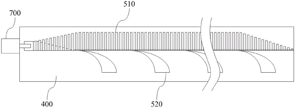

Embodiment Construction

[0022] The following will clearly and completely describe the technical solutions in the embodiments of the present invention with reference to the accompanying drawings in the embodiments of the present invention. Obviously, the described embodiments are only some, not all, embodiments of the present invention. Based on the embodiments of the present invention, all other embodiments obtained by persons of ordinary skill in the art without making creative efforts belong to the protection scope of the present invention.

[0023] Before introducing the technical solution of the present invention, some technical terms need to be explained.

[0024] Microwave surface plasmons are plasmons in the microwave frequency band. By etching periodic or quasi-periodic sub-wavelength metal unit structures on the surface of the medium, the boundary conditions of the incident electromagnetic wave are changed to make it exponentially attenuate in the normal direction of the interface. while pro...


PUM


Abstract

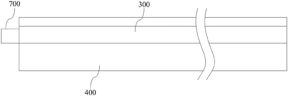
The invention discloses a high performance wide angle domain frequency scanning antenna based on microwave surface plasmon and is different form traditional frequency scanning antennas. According to the frequency scanning antenna, different metal unit structures are etched on a medium surface, electromagnetic waves are coupled to be microwave surface plasmons, and the microwave surface plasmons are radiated in a conduction process. The frequency scanning antenna is advantaged in that the frequency scanning antenna is manufactured through employing the printed circuit board technology, sub-wavelength thickness and a plane structure have properties of wide scanning angle domain, linear scanning angle distribution and strong designability, and the frequency scanning antenna can be applied to engineering practices.

Description

technical field [0001] The invention relates to the technical field of antennas, in particular to frequency scanning antennas based on microwave surface plasmons. Background technique [0002] The antenna mainly completes in the wireless communication equipment: 1. energy conversion function; 2. directional radiation (or reception) function. With the rapid development of radio technology and the increasing application of radio equipment, various types of antennas have emerged, and frequency scanning antennas are one of them. The phase of the wave in the frequency scanning antenna is a function of frequency, so the beam pointing angle changes regularly and in a large range with a small change in the operating frequency, referred to as the frequency scanning antenna, and is mainly used for high data rate three-coordinate radar. [0003] Common forms of existing frequency-swept antennas include leaky-wave antennas, frequency-scanned array antennas, and the like. Leaky-wave an...

Claims


Application Information

Patent Timeline
Patent Type & Authority Applications(China)
IPC IPC(8): H01Q1/38H01Q1/48H01Q1/50
CPCH01Q1/38H01Q1/48H01Q1/50
Inventor 李勇峰韩亚娟张介秋屈绍波马华王甲富庞永强王军
Owner AIR FORCE UNIV PLA
Why Eureka
Try Eureka