Dual band radio frequency (RF) and optical communications antenna and terminal design methodology and implementation

a dual-band radio frequency and optical communication technology, applied in the direction of antennas, simultaneous aerial operations, electrical apparatus, etc., can solve the problems of inapplicability of optical link availability, in rf terms, cassegrain layouts at microwave frequencies such as such relatively small apertures, and achieve link robustness and enhanced system capabilities

Active Publication Date: 2012-01-10
THE JOHN HOPKINS UNIV SCHOOL OF MEDICINE
View PDF13 Cites 234 Cited by
  • Summary
  • Abstract
  • Description
  • Claims
  • Application Information

AI Technical Summary

Benefits of technology

[0006]The present invention provides a dual-band (optical / RF) antenna with a single shared, high-precision (mirror quality) aperture for optical and RF communications using a lightweight structure to minimize mass and volume, while maintaining the high performance efficiency of each individual mode. The novel antenna design is reciprocal in both regimes, accommodating transmission and reception of both optical and radio frequency energies with maximum efficiency (near diffraction-limited performance). The optical mode provides a high bandwidth extremely directive optical link, while the RF mode provides a lower bandwidth wider beam link, well suited for maintaining connectivity during adverse weather conditions, such as clouds. The RF band also accommodates traditional navigation techniques, and assists in cueing the extremely tight optical beam. The antenna is well-suited for far-range (e.g., >100 km terrestrial) to extremely far-range (space-to-ground) link distances.
[0008]According to another aspect of the present invention, the dual-band (optical / RF) antenna is built around a near-diffraction-limited high performance primary mirror which is shared by both the direct-fed (prime-focus) RF antenna design and a Cassegrain optical telescope. The dual-band antenna provides a collimated optical beam interface at its vertex to allow straightforward integration with an optical transceiver to be situated behind the primary mirror, i.e., the Cassegrain acts like an afocal telephoto / beam expander. The optical portion of a typical laser communications (lasercom) transceiver would necessarily consist of a radiating source, optical interface and distribution train, and a fast-steering loop, all mounted on a vibration isolated mini-optical bench with adequate heat dissipation for the laser. A particular transceiver configuration of note which the high precision aperture enables is one which achieves fiber-coupling of the received optical beam using adaptive optics behind the primary mirror.
[0010]According to one aspect, the disclosed dual-band antenna exploits material properties to allow the two modes of operation to be co-boresighted while using a direct feed system for the RF and a Cassegrain system for the optics. The combination of a co-boresighted optical imaging-quality aperture, applicable to a variety of desirable functions (i.e., communications, imaging, sensing) with an RF communications and / or sensing aperture, achieves both link robustness and enhanced systems capabilities.

Problems solved by technology

To compensate, however, for link losses and availability from space platforms directly to ground sites, dual-band (optical / RF) technologies are desirable because optical link availabilities even with site diversity are problematic.
Optical reflectors (mirrors) are also typically flatter (i.e., having higher f / #) than RF reflectors of similar size due to the difficulty of fabricating highly precise curved surfaces over large diameters.
However, Cassegrain layouts at microwave frequencies for such relatively small apertures, in RF terms, are not practical.

Method used


Image

  • Dual band radio frequency (RF) and optical communications antenna and terminal design methodology and implementation
  • Dual band radio frequency (RF) and optical communications antenna and terminal design methodology and implementation
  • Dual band radio frequency (RF) and optical communications antenna and terminal design methodology and implementation

Examples


Embodiment Construction

1. Introduction

[0019]In the following discussion, numerous specific details are set forth to provide a thorough understanding of the present invention. However, those skilled in the art will appreciate that the present invention may be practiced without such specific details. In other instances, well-known elements have been illustrated in schematic or block diagram form in order not to obscure the present invention in unnecessary detail. Additionally, for the most part, details concerning network communications, electromagnetic signaling techniques, and the like, have been omitted inasmuch as such details are not considered necessary to obtain a complete understanding of the present invention and are considered to be within the understanding of persons of ordinary skill in the relevant art.

2. Overview

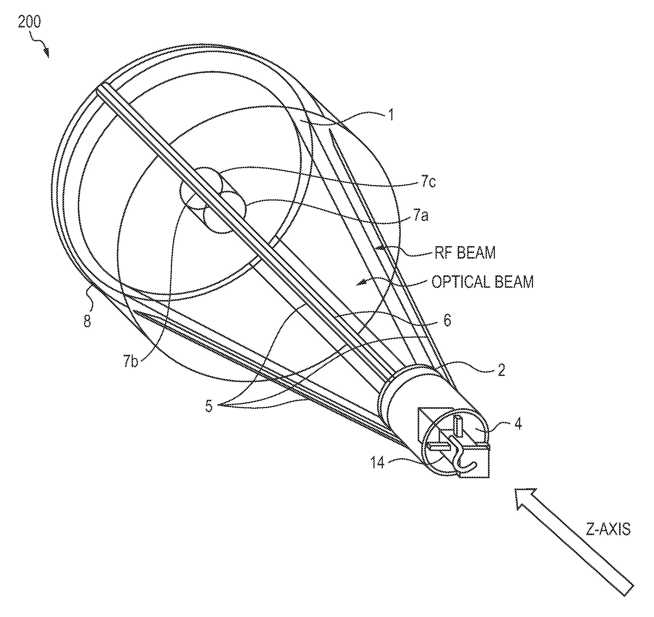
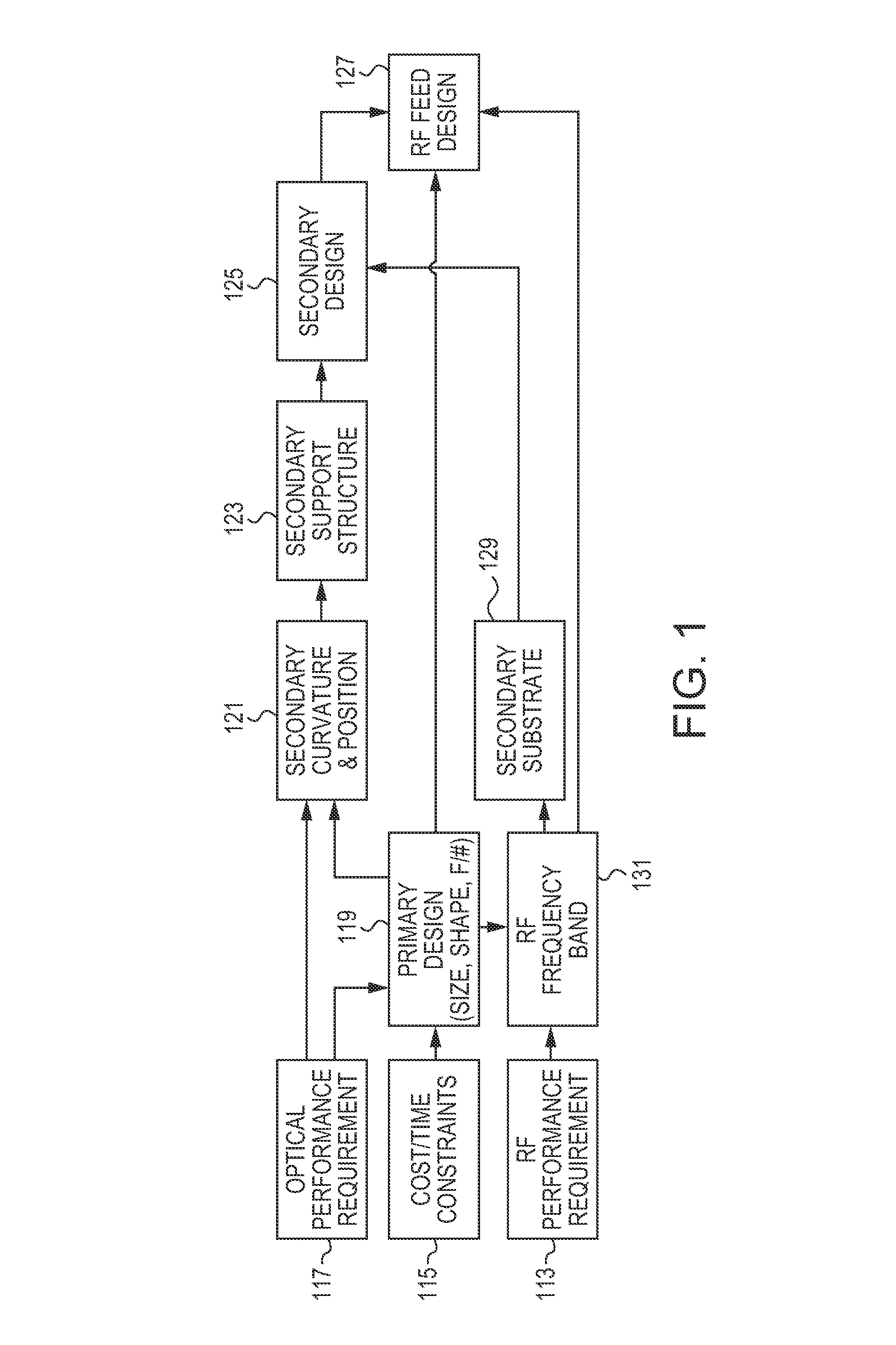
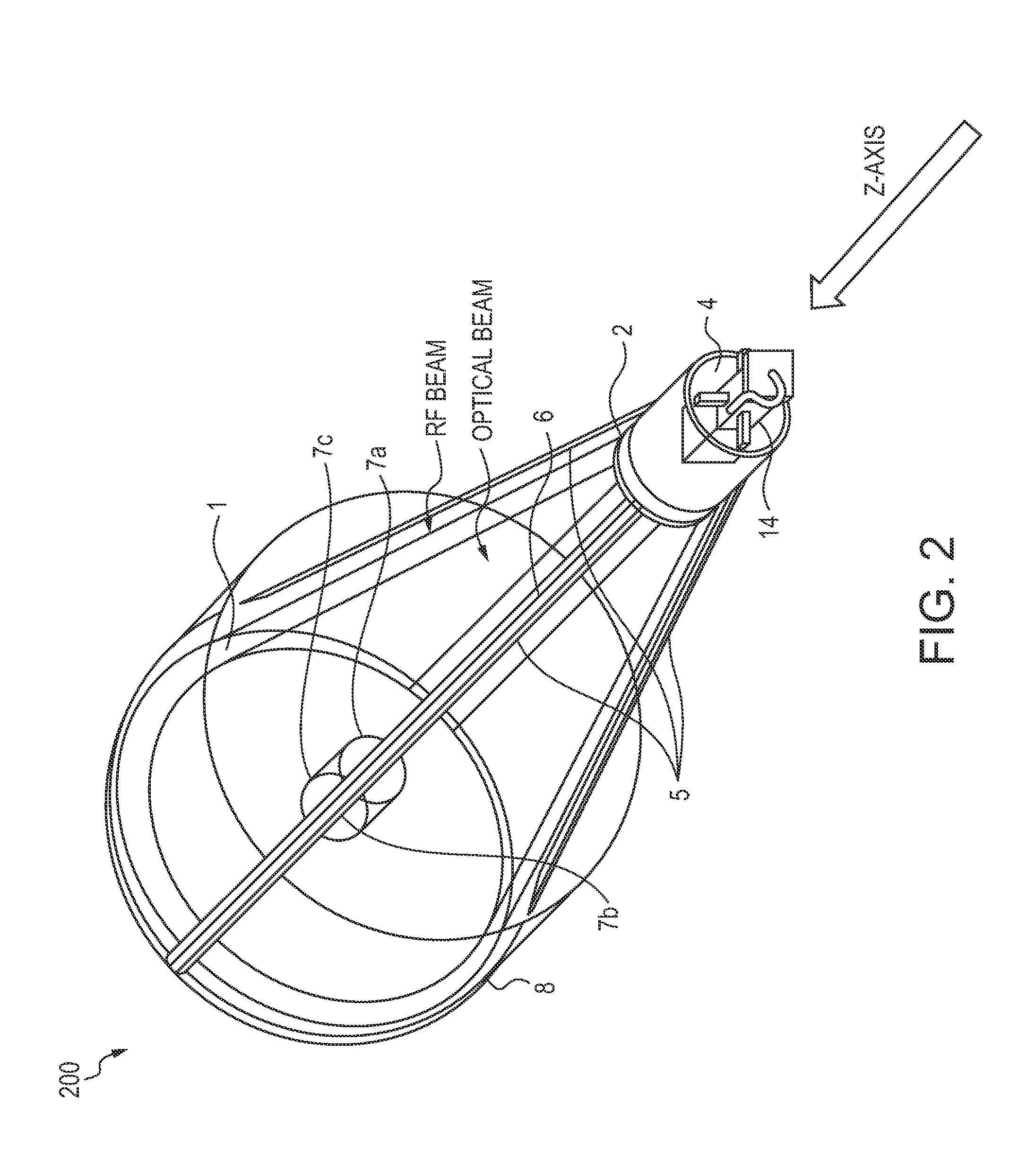
[0020]The combination of both optical and RF communications bands into a single optimized, compact system design aperture realizes a highly capable and efficient communications termina...


PUM


Abstract

A dual-band antenna is provided that combines two normally disparate communications modes into a single compact aperture minimizing overall mass and volume, while maintaining high performance efficiency and reciprocity of each individual mode. The antenna is compatible with both optical (near-IR / visible) and RF (microwave / millimeter-wave) transceiver subsystems for high bandwidth communications, applicable primarily to long- to extremely long-range (space-to-ground) link distances. The optical link provides high bandwidth while the RF provides a lower data-rate weather backup, accommodation for traditional navigation techniques, and assistance in cueing the extremely tight optical beam by matching the RF beamwidth to an optical fine-steering mechanism field-of-regard. The configuration is built around a near-diffraction-limited high performance primary mirror shared by both a direct-fed RF antenna design and a Cassegrain optical telescope. Material properties are exploited to combine the optical secondary mirror with the RF feed structure, providing a collimated optical beam interface at the antenna vertex.

Description

BACKGROUND OF THE INVENTION[0001]1. Field of the Invention[0002]The present invention relates generally to antennas and more particularly to a dual-band, RF and optical antenna with a shared aperture for optical as well as microwave communications using a single compact and highly efficient structure. The present invention also relates to the optimal communication system attributes that drive the antenna design, the RF and optical mode control logic, and the multi-channel receiver implementation that collectively support optimal operation under limited availability conditions from space to ground.[0003]2. Description of the Related Art[0004]There is increasing need for very high data rate communications for critical data transfer and command-control-communication systems for military reconnaissance and situational awareness from space. It is also desirable to be able to project this data directly to one or more users in a specific theater, as opposed to routing the data through Cont...

Claims


Application Information

Patent Timeline
Patent Type & Authority Patents(United States)
IPC IPC(8): H01Q21/00
CPCH01Q13/0208H01Q5/22H04B10/1121
Inventor BRUZZI, JONATHAN R.BOONE, BRADLEY G.
Owner THE JOHN HOPKINS UNIV SCHOOL OF MEDICINE
Why Eureka
Try Eureka