Electro-luminescent wire

Active Publication Date: 2016-08-25
CONSEQUOR SA
View PDF0 Cites 0 Cited by
  • Summary
  • Abstract
  • Description
  • Claims
  • Application Information

AI Technical Summary

Benefits of technology

[0008]The idea on which the present invention is based is that of replacing the solid luminescent layer of an electro-luminescent wire with a luminescent gelatinous substance having a greater light emission capacity in presence of an electromagnetic field, and associating the gelatinous substance to the co

Problems solved by technology

Such electro-luminescent wires reveal some structural drawbacks, which are observed in the light emission capacity thereof, and other drawbacks related to the method of production thereof.
In particular, during the solidification of the mixture around the conductors in the solid luminescent layer, the molecular structure of the dielectric liquid and of the luminescent material on which the mixture is based is subjected to some alterations which reduce the light emission capacity thereof.
Actually, solidification causes some micro-cracks, i.e. microscopic cracks and discontinuity in the solid luminescent layer, which considerably reduce the light emission of the layer in presence of the electromagnetic field.
F

Method used


Image

  • Electro-luminescent wire
  • Electro-luminescent wire
  • Electro-luminescent wire

Examples


Example

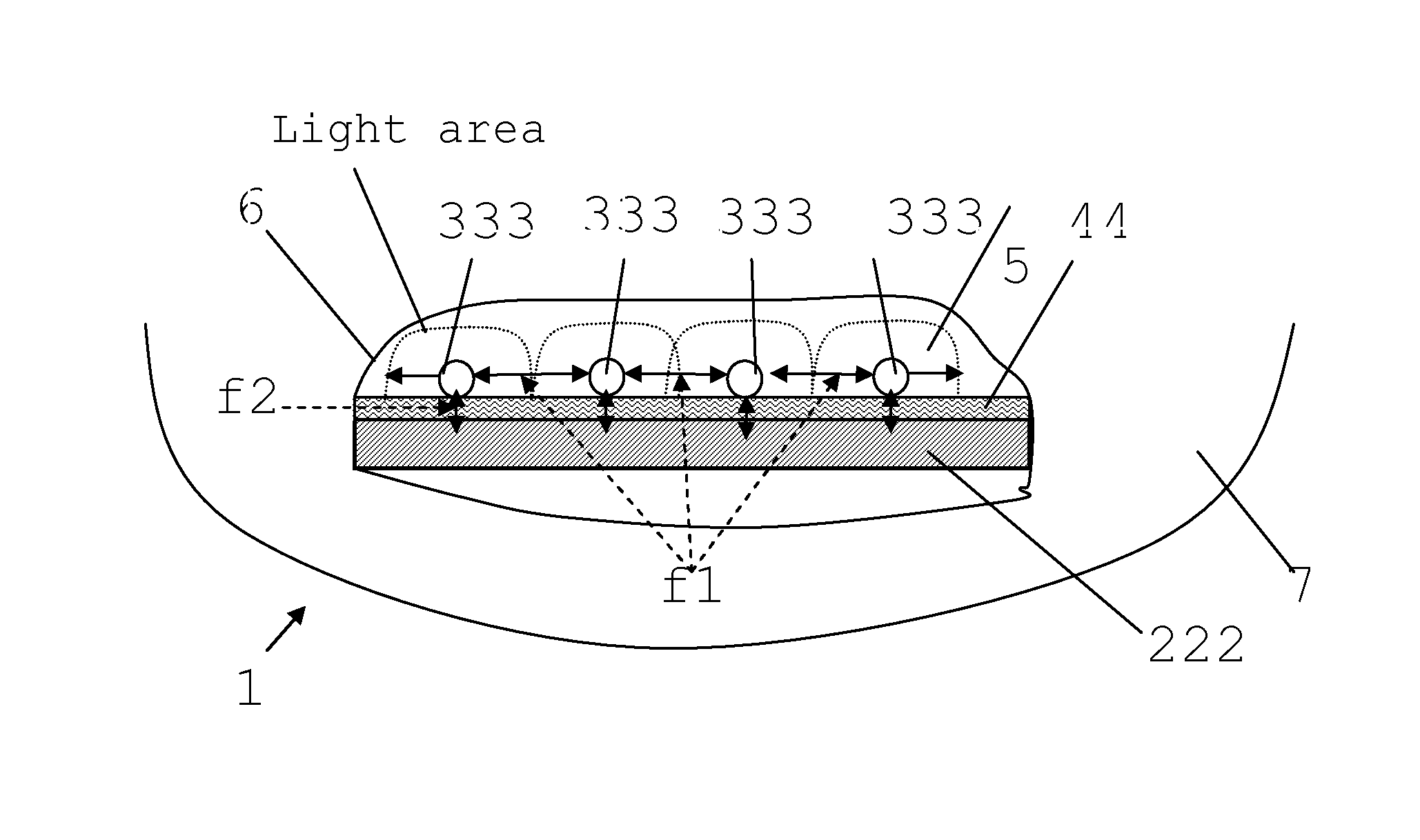
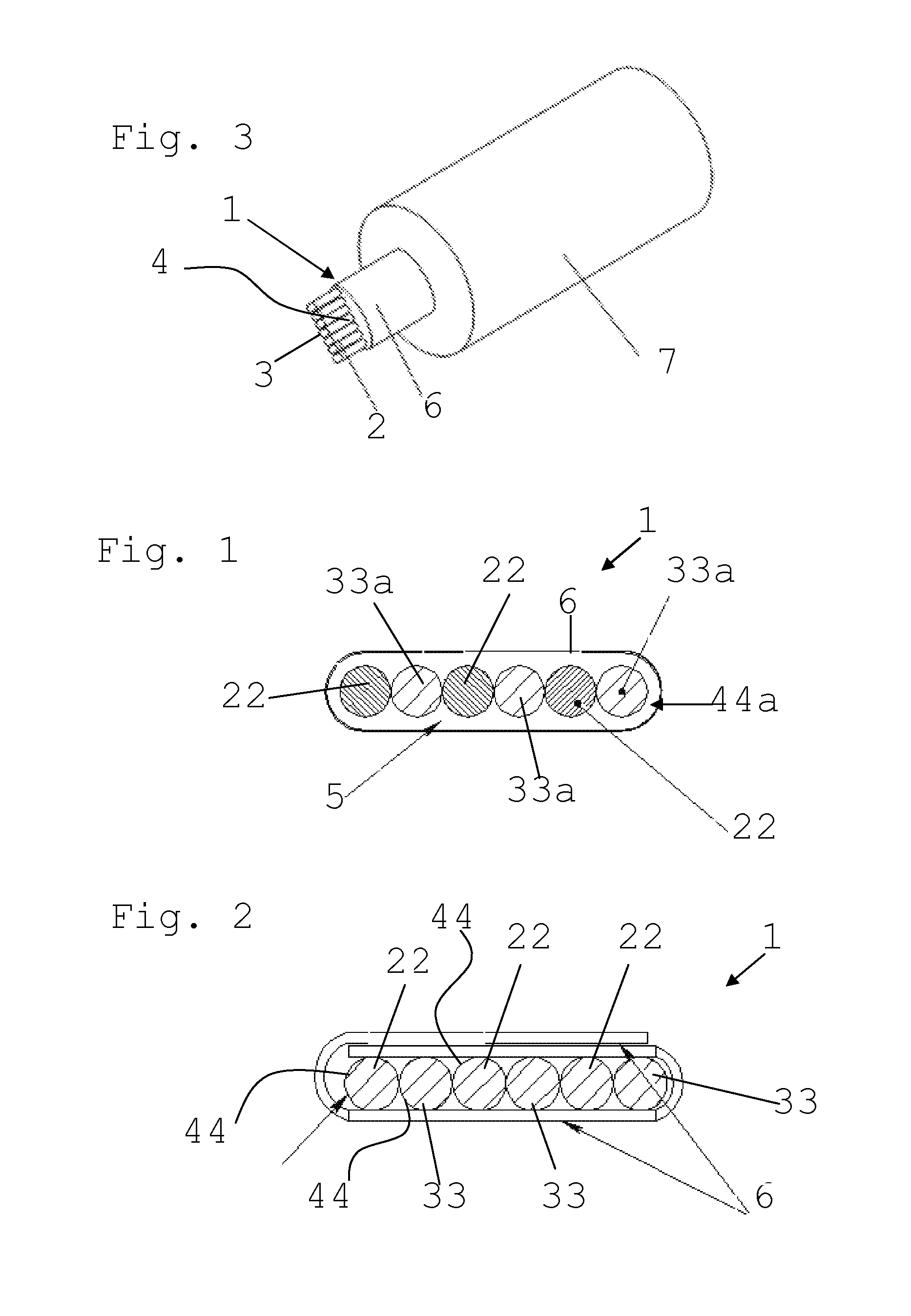
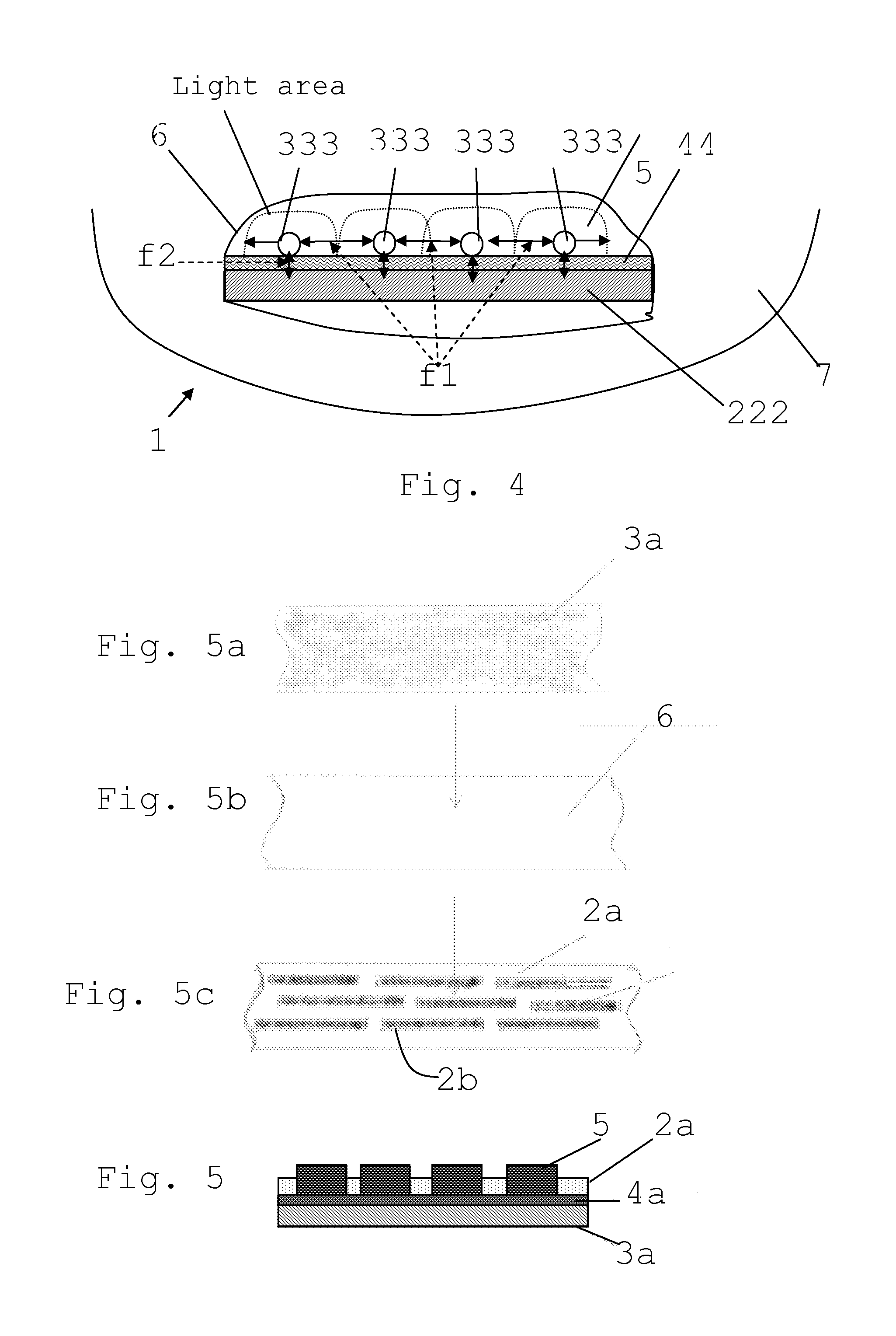
[0032]With reference to FIG. 1 an electro-luminescent wire according to the present invention, comprising a transparent plastic film 6, a luminescent gelatinous substance 5 enclosed by the film 6, and conductors 22, 33a substantially submerged in the luminescent gelatinous substance 5 is schematically represented and indicated with 1. The conductors 22, 33a are drawn very close to each other but a predetermined interspace in which there is the luminescent gelatinous substance 5 is provided therebetween. The conductors 22, 33a are for example parallel conductor wires which can be power-supplied in alternating current; in particular, the conductor wires 33a are connectable to a first polarity of an electric power supply while the conductor wires 22 are electrically connectable to the reversed polarity. The wires 33a are covered by an insulator or sheath 44a to avoid a short-circuit with the wires 22, due to the presence of luminescent gelatinous substance which serves as a conductor. ...


PUM


Abstract

The invention describes an electro-luminescent wire comprising at least two conductors, having substantially longitudinal extensions, parallel to each other and insulated electrically, the conductors being supplied electrically to generate an electromagnetic field therebetween. A luminescent gelatinous substance covers at least one of the conductors and a transparent plastic film encloses the luminescent gelatinous substance and the conductors; the luminescent gelatinous substance emits light in presence of an electromagnetic field generated by the conductors.

Description

FIELD OF APPLICATION[0001]The present invention refers to an electro-luminescent wire comprising at least two conductors having a substantially longitudinal extension, parallel to each other and insulated as well as a luminescent material; the conductors are supplied electrically to generate an electromagnetic field in whose presence the luminescent material emits light. The invention also refers to a method for producing an electro-luminescent wire of the aforementioned type.PRIOR ART[0002]As known, an electro-luminescent wire comprises a first and a second conductor and a solid luminescent layer between the two conductors. For example the conductors are wires and the solid luminescent layer is a coating made of luminescent material, solidified externally with respect to the wire. In particular, the first and the second conductor are supplied electrically, with reverse polarities of an alternating current AC, to generate an electromagnetic field therebetween; such field excites the...

Claims


Application Information

Patent Timeline
IPC IPC(8): H05B33/26H05B33/10H05B33/04H05B33/14
CPCH05B33/145H05B33/26H05B33/10H05B33/04
Inventor CHERNASHKIN, GENNADY
Owner CONSEQUOR SA
Why Eureka
Try Eureka