Apparatus and method for prilling a liquid, preferably urea melt

Inactive Publication Date: 2017-09-28
CASALE SA
View PDF6 Cites 2 Cited by
  • Summary
  • Abstract
  • Description
  • Claims
  • Application Information

AI Technical Summary

Benefits of technology

[0013]The invention aims to overcome the aforementioned problems and drawbacks of the prior art. In greater detail, the invention aims to provide an apparatus for prilling a liquid, which is applicable to both the shower-head and rotating-bucket type prilling plants and which is able, over the prior art, to achie

Problems solved by technology

This solution, however, has not proved to be entirely satisfactory.
Both these solutions, however, have a number of drawbacks and disadvantages which are yet to be overcome.
Imparting vibrations directly to the fluid mass is theoretically advantageous and simple from a constructional point of view, but it has been found that this process is difficult to control and very sensitive to external disturbances.
Therefore any divergence from the laminar flow condition may disturb the vibrations transmitted to the liquid jets and adversely affect the operation.
The method of vibrating the bucket, or its perforated wall, solves at least partly these problems because, downstream of the perforated wal

Method used


Image

  • Apparatus and method for prilling a liquid, preferably urea melt
  • Apparatus and method for prilling a liquid, preferably urea melt
  • Apparatus and method for prilling a liquid, preferably urea melt

Examples


Example

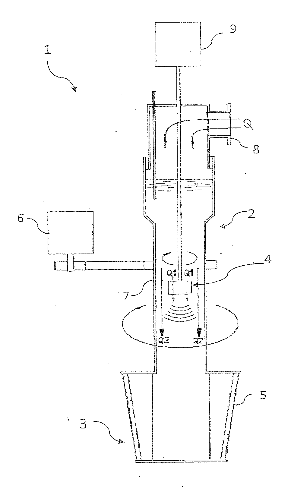
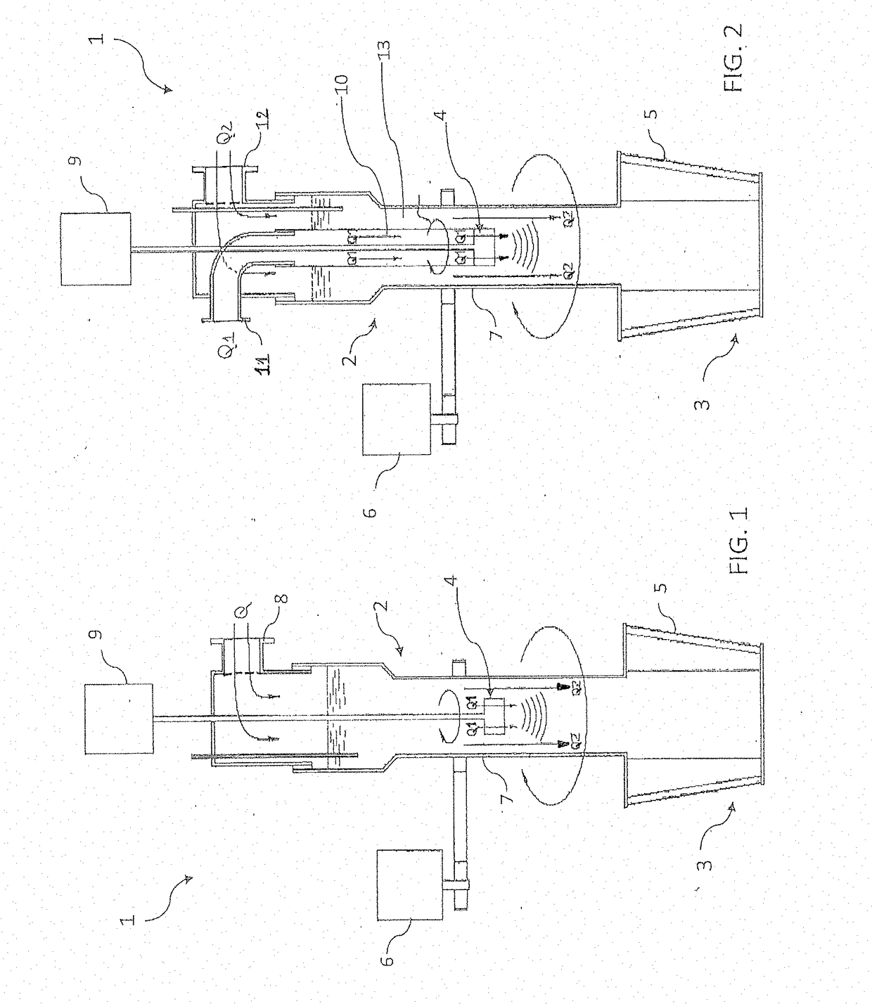
[0064]FIG. 1 is a schematic illustration of a prilling apparatus denoted generally by 1, intended for prilling a stream of urea melt Q. Said apparatus 1 is located at the top of a prilling tower (not shown).

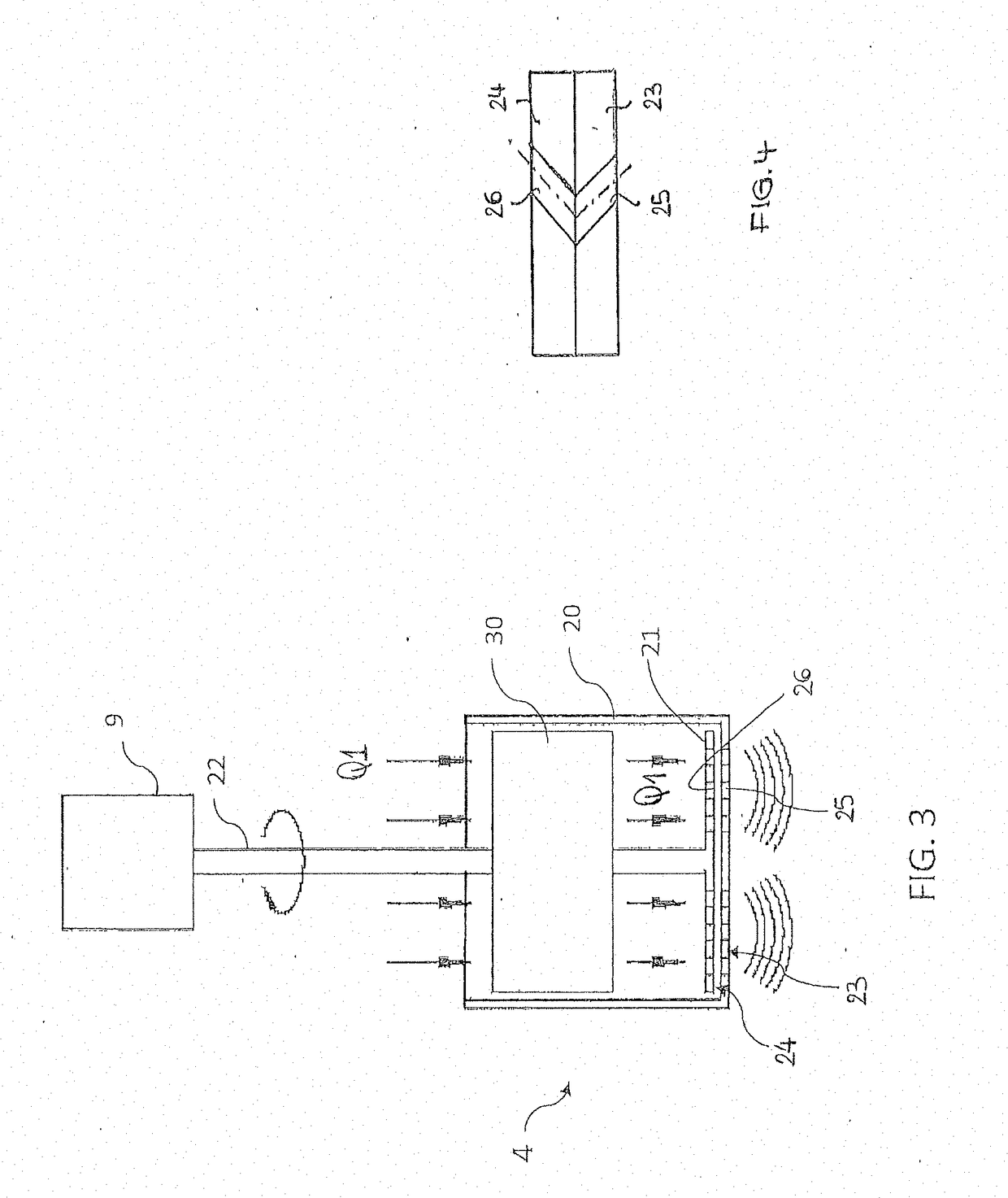
[0065]Said prilling apparatus 1 comprises essentially a urea supply distributor 2, a dispenser formed by a rotating bucket 3 and a pulse generator 4 which in this example is housed inside the dispenser 2.

[0066]The bucket 3 has a perforated wall 5 and is made to rotate by a first motor 6; more particularly the motor 6 drives rotationally a tube 7 (which is part of the distributor 2) with which the bucket 3 or at least the perforated wall 5 is integral.

[0067]The urea melt Q is introduced into the distributor 2 via an inlet 8 and travels along the tube 7 until it reaches the bucket 3. As can be noted in the figure, the pulse generator 4 is passed through by the flow Q or by a part thereof. In the example shown in FIG. 1, said generator 4 has a smaller cross-section than the tube 7 a...


PUM

PropertyMeasurementUnit
Angleaaaaaaaaaa
Angleaaaaaaaaaa
Pressureaaaaaaaaaa

Abstract

Apparatus for prilling a liquid, comprising a distributor for supplying said liquid, at least one dispenser, and a pulse generator, wherein said pulse generator: is situated in either one of said supply distributor and said dispenser; is passed through by at least a portion of said liquid; and comprises at least a first surface and a second surface, which face each other and perform a relative movement and comprise respective passages for the liquid; and wherein said first surface and second surface, which are passed through by the liquid, generate in the liquid periodic pulses of pressure having a predetermined frequency dependent on the relative speed of said two surfaces.

Description

FIELD OF APPLICATION[0001]The invention relates to an apparatus for prilling a liquid, preferably for urea. In particular the invention relates to a prilling apparatus which can be applied both to shower-head type prilling towers and to rotating-bucket prilling towers.PRIOR ART[0002]Prilling apparatuses constitute a known technology for converting a liquid product into solid form, consisting of grains of a desired size.[0003]Prilling technology is for example widely used for the production of urea. A plant for the production of commercial solid urea comprises a synthesis section which produces urea melt and a finishing section for converting the urea melt into a solid product. Said finishing section, in many plants, uses prilling technology. The known methods for urea synthesis and finishing are described in literature, for example in Ullmann's Encyclopedia of Industrial Chemistry, Wiley-VCH Verlag, vol. A27.[0004]The prilling process essentially consists in the cooling and solidifi...

Claims


Application Information

Patent Timeline
IPC IPC(8): B01J2/18B05B7/14B01J2/04
CPCB01J2/18B05B7/1459B01J2/04
Inventor RIZZI, ENRICOBEDETTI, GIANFRANCO
Owner CASALE SA
Why Eureka
Try Eureka