Drain tube for a low-pressure shaft of a turbomachine

Inactive Publication Date: 2006-11-16
SN DETUDE & DE CONSTR DE MOTEURS DAVIATION S N E C M A
View PDF5 Cites 3 Cited by
  • Summary
  • Abstract
  • Description
  • Claims
  • Application Information

AI Technical Summary

Benefits of technology

[0005] A main object of the present invention is thus to mitigate such drawbacks by proposing a drain tube that ena

Problems solved by technology

The main problem lies in the modulus/density ratio of the metal which requires intermediate fastener supports to be installed between the low-pressure shaft and the tube in order to prevent any radial displacement of the tube inside the shaft wh

Method used


Image

  • Drain tube for a low-pressure shaft of a turbomachine
  • Drain tube for a low-pressure shaft of a turbomachine

Examples


Embodiment Construction

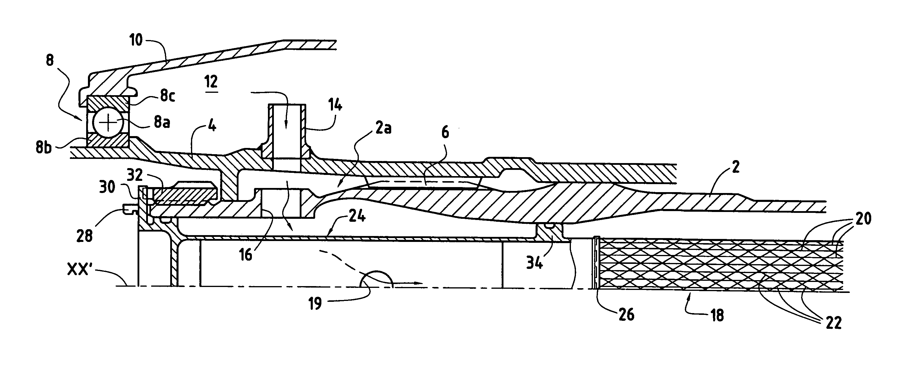
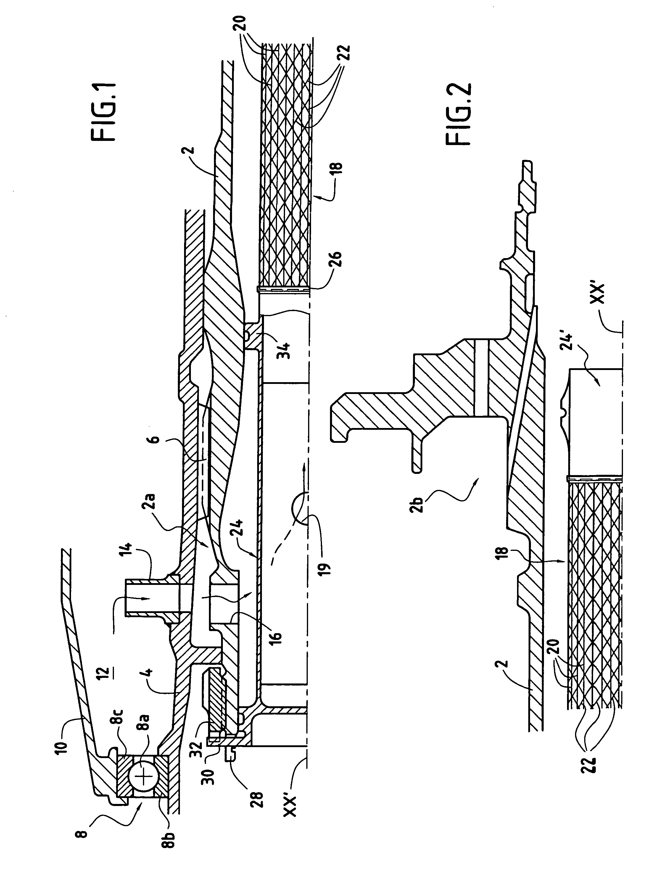
[0015] As shown in FIG. 1, reference 2 designates part of a low-pressure shaft of a turbomachine. This shaft 2 of longitudinal axis XX′ is hollow and extends along practically the entire length of the turbomachine. At its upstream end 2a, it drives rotation of the fan shaft 4 via fluting 6. The fan shaft 4 is disposed coaxially around the low-pressure shaft 2.

[0016] Moving fan blades (not shown) are fastened to the upstream end of the fan shaft 4. The fan shaft 4 is also supported to rotate by a rolling bearing 8. This bearing 8 is made up, for example, of balls 8a inserted between an inner ring 8b mounted on the fan shaft 4 and an outer ring 8c mounted on a shaft 10.

[0017] An oil feed circuit (not shown) serves to convey and inject oil between the rings 8b, 8c of the rolling bearing 8 in order to lubricate and cool it. The lubrication and cooling oil is confined in an oil enclosure 12 defined in particular by the fan shaft 4 and the shaft 10 to which the outer ring 8c of the bear...


PUM


Abstract

The invention provides a drain tube for mounting coaxially inside a low-pressure shaft of a turbomachine, the tube comprising a hollow metal tubular portion of length substantially identical to that of the shaft inside which said tube is to be mounted, the outside surface of the metal portion of the tube being covered over at least a fraction of its length in a composite material based on fibers oriented along a direction that is substantially longitudinal so as to confer bending strength to the tube.

Description

BACKGROUND OF THE INVENTION [0001] The present invention relates to the general field of drain tubes for mounting inside the low-pressure shaft of a turbomachine. [0002] In a turbomachine, the shaft of the low-pressure spool, referred to below as the low-pressure shaft, drives rotation of the fan shaft at its upstream end. This fan shaft is supported to rotate in a rolling bearing which needs to be lubricated and cooled. For this purpose, oil is injected between the rings of the rolling bearing by a feed circuit. The oil is confined in an enclosure in which it mixes with air prior to being exhausted to the exhaust casing of the turbomachine by flowing inside the low-pressure shaft. [0003] In order to ensure that the oil flowing inside the low-pressure shaft does not damage the low-pressure shaft, particularly by coking thereon, it is known to mount a hollow oil-removal tube concentrically inside the shaft, which tube is referred to herein as a drain tube. Drain tubes must satisfy ce...

Claims


Application Information

Patent Timeline
IPC IPC(8): F02C7/06F01D5/08F01D25/20
CPCF01D5/085F02C7/06F01D25/20
Inventor DAMBRINE, BRUNOHUGONIE, AYMERICMONS, CLAUDESOUPIZON, JEAN-LUC
Owner SN DETUDE & DE CONSTR DE MOTEURS DAVIATION S N E C M A
Why Eureka
Try Eureka