Protective Tool Cover
- Summary
- Abstract
- Description
- Claims
- Application Information
AI Technical Summary
Benefits of technology
Problems solved by technology
Method used
Image

Examples
Example
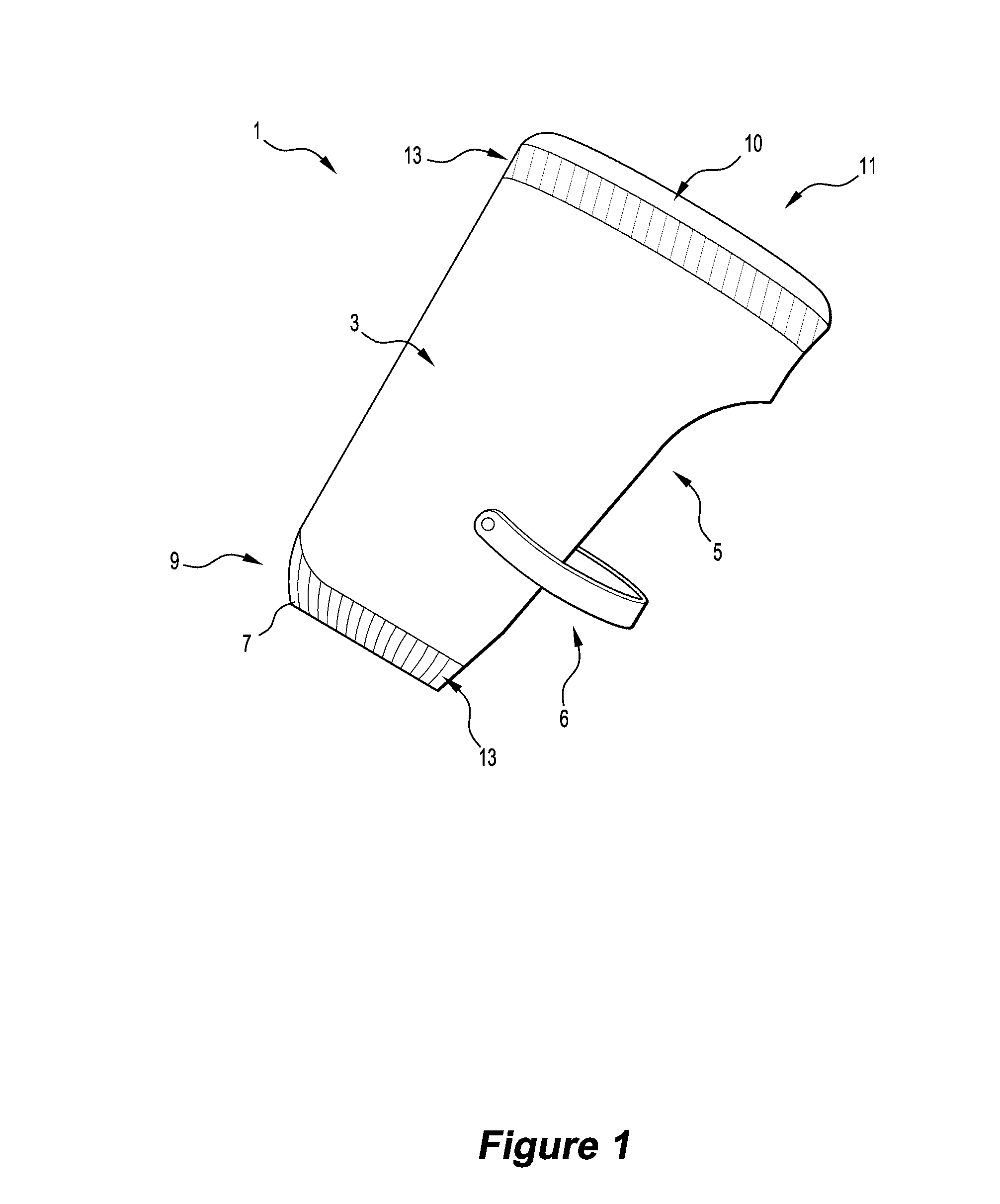
[0047]For the purposes of the description the first embodiment of the cover 1 formed of compliant, reusable, material will be referred to herein.
[0048]The cover 1 comprises a boot 3 which can be formed of any generally compliant material capable of absorbing impacts or shock and returning to its original shape. Suitable materials include natural and synthetic rubbers; neoprene and any one of a range of available synthetic materials.
[0049]The configuration of the boot 3 is such to generally conform to the generic shape of the tool 2 in question and. in particular configured to provide protection for the most vulnerable parts of the tool 2 which can suffer damage upon dropping from a height with the damage general directed to the casing as the tool hits the ground.
[0050]The cover 1 comprises a boot 3 and a fixing means 6, wherein the boot 3 is made of generally unitary construction having an open side 5 adapted for insertion of the tool 2.
[0051]The open side 5 is of sufficient size to...
Example
[0077]Turning to FIGS. 7 and 8, which illustrate a second embodiment of the invention: the cover 101 is formed from a first layer of material that is shaped with darts 122. These darts 122 or pleats provide form and general shape to the boot 103, assisting with stretching the boot 103 over the tool 102.
[0078]In this second embodiment, the cover 101 comprises a boot 103 and an outer skin 117, thereby providing at least two layers of material to protect the damage prone regions of the tool 102. At least one of the boot 103 or the outer skin 117 is energy absorbent. Preferably, each layer of the boot 103 and the outer skin 117 is energy absorbent to provide additional protection for the tool 102.
[0079]As illustrated in FIGS. 7 and 8, the outer skin 117 is not tailored to the same template as the boot 103, thereby giving further shape to the cover 101 by tensioning the material and taking the general form of a tool 102 before being stretched over the tool 102.
[0080]The outer skin 117 ca...
Example
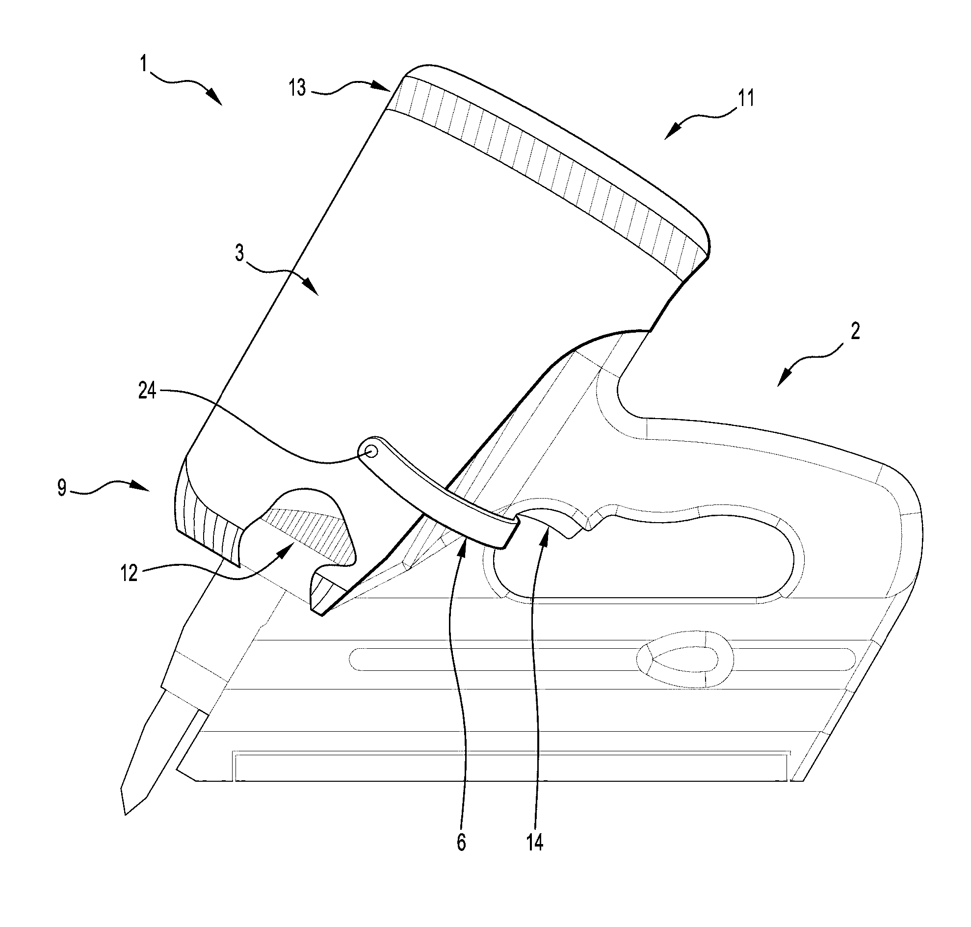
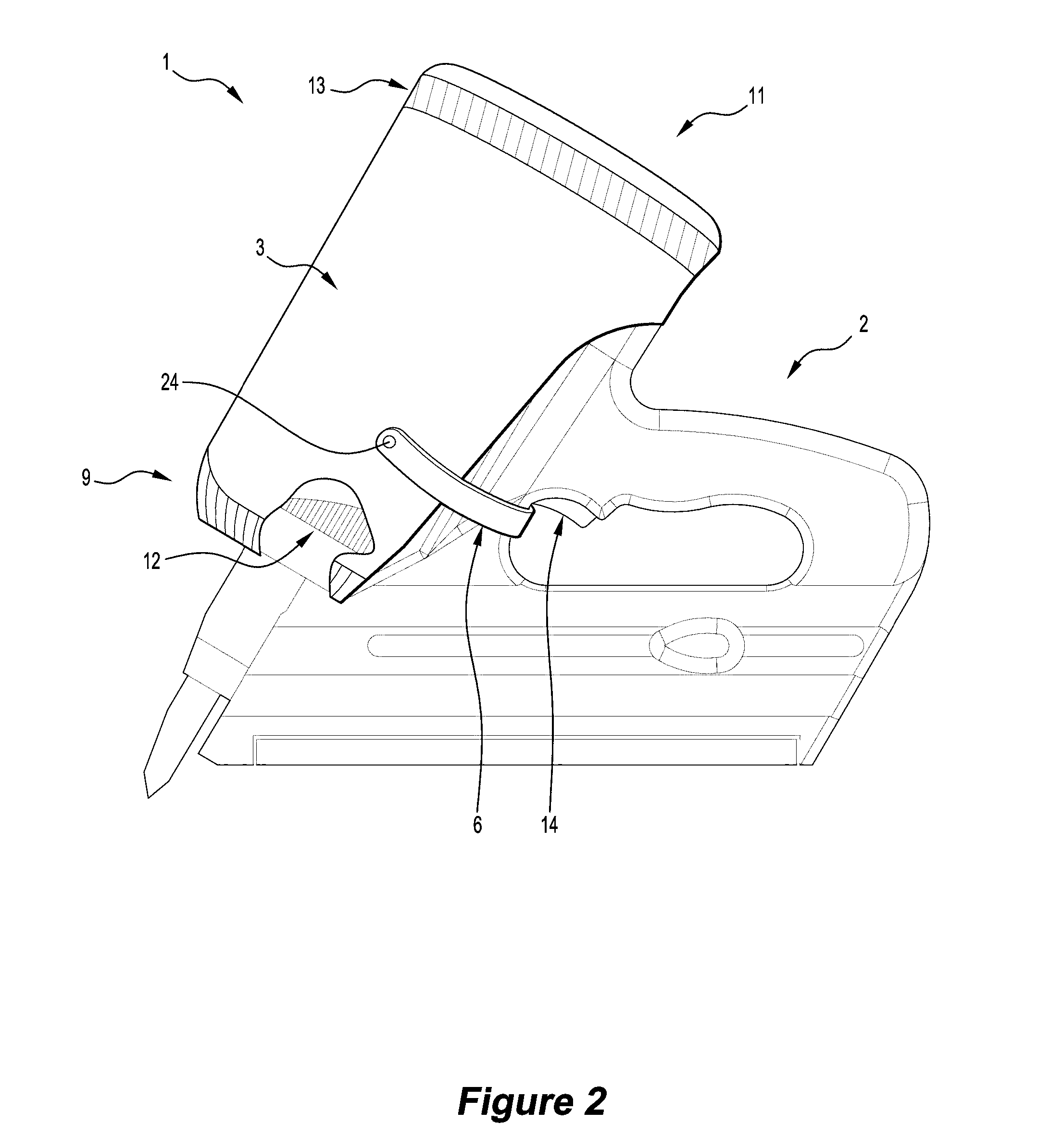
[0097]In a third embodiment the cover 201 is provided with a secondary layer 217 and a tertiary layer 223 of energy absorbing material, as illustrated in FIGS. 9 and 10.
[0098]This third embodiment provides protection for a larger form of tool 202, referred to as a “framer”. The framer expels a large, heavy duty nail, and as such is expelled from a larger and heavier tool 202. To account for the additional weight of some tools 202, the cover 201, provides a tertiary layer 223 of neoprene or alternative energy absorbing material, to provide additional impact resistance. The cover 201 illustrated in FIGS. 9 and 10 also uses darts 222 to shape the boot 203 to a tool 202 and provides side air vents 219 and a fixing means 206 having an adjustor 224 in the form of a buckle.
[0099]To provide further protection to heavier tools 202, the base 220 of the cover 201 is manufactured from a material having additional energy absorbing capabilities. Alternatively, the base 220 is configured, to be th...
PUM
| Property | Measurement | Unit |
|---|---|---|
| Flow rate | aaaaa | aaaaa |
| Shape | aaaaa | aaaaa |
| Deformation enthalpy | aaaaa | aaaaa |
Abstract
Description
Claims
Application Information
 - R&D Engineer
- R&D Manager
- IP Professional
- Industry Leading Data Capabilities
- Powerful AI technology
- Patent DNA Extraction
Browse by: Latest US Patents, China's latest patents, Technical Efficacy Thesaurus, Application Domain, Technology Topic.
© 2024 PatSnap. All rights reserved.Legal|Privacy policy|Modern Slavery Act Transparency Statement|Sitemap