
Fence Post Straightener

a technology of straightener and fence post, which is applied in the direction of wrenches, building types, constructions, etc., can solve the problems of steel posts becoming twisted about their cross-section

Active Publication Date: 2016-10-06
TRACTOR SUPPLY COMPANY
View PDF5 Cites 2 Cited by
  • Summary
  • Abstract
  • Description
  • Claims
  • Application Information

AI Technical Summary

Benefits of technology

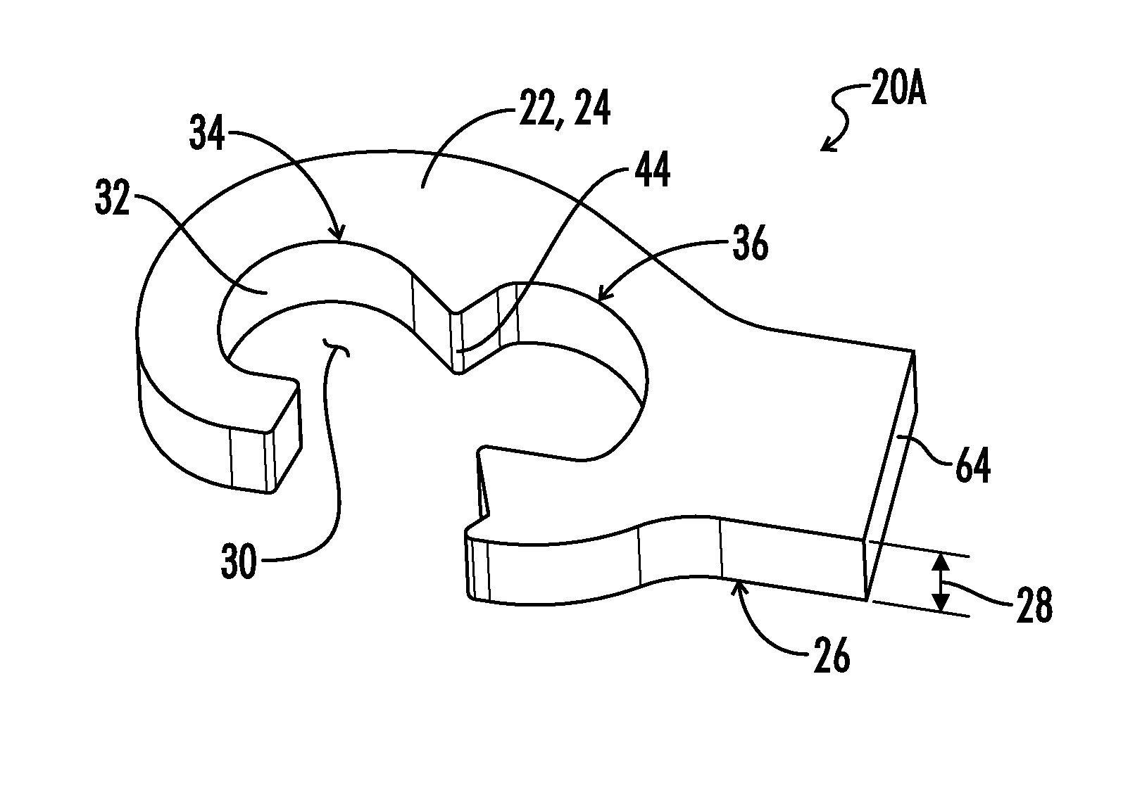
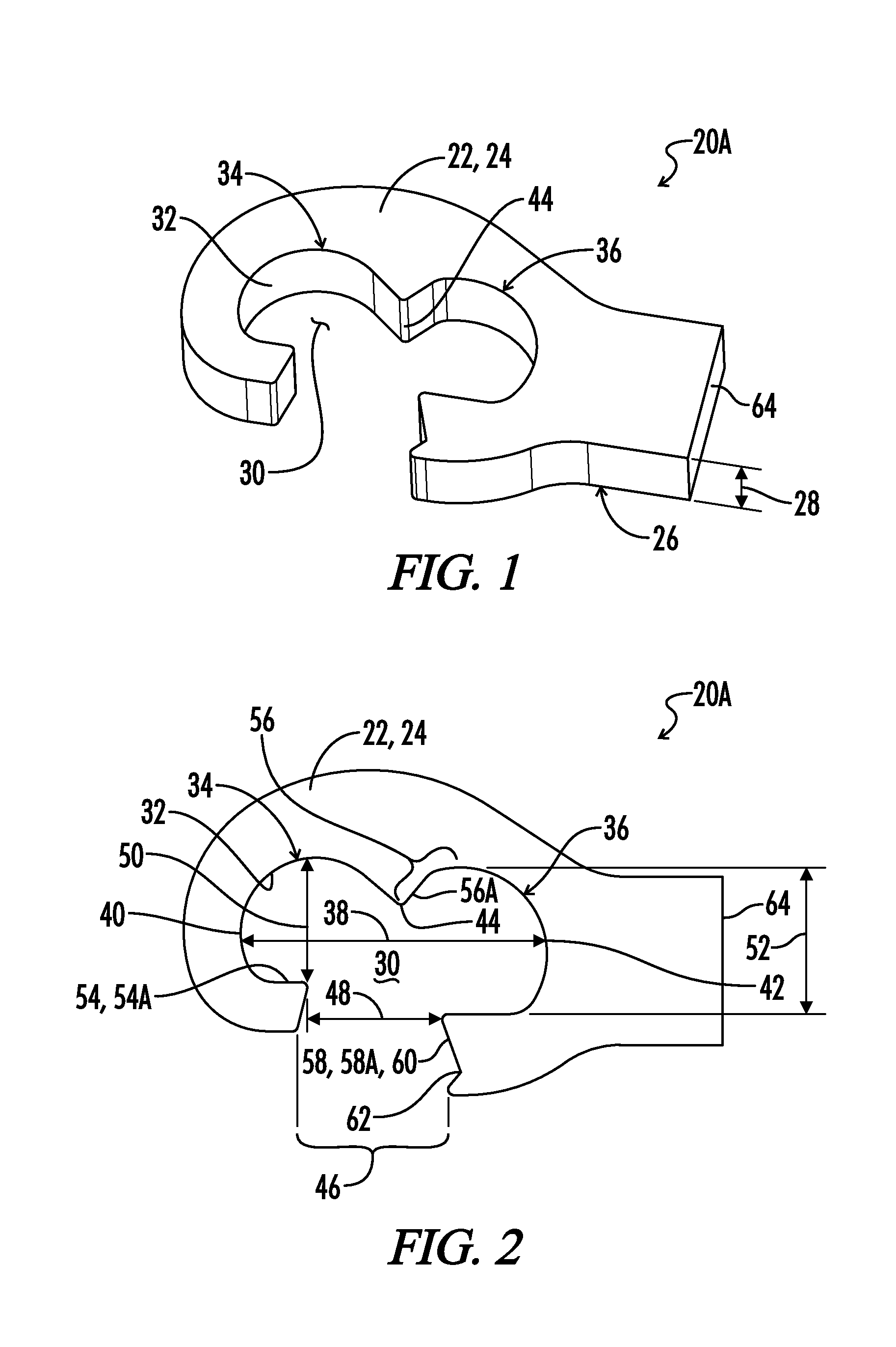
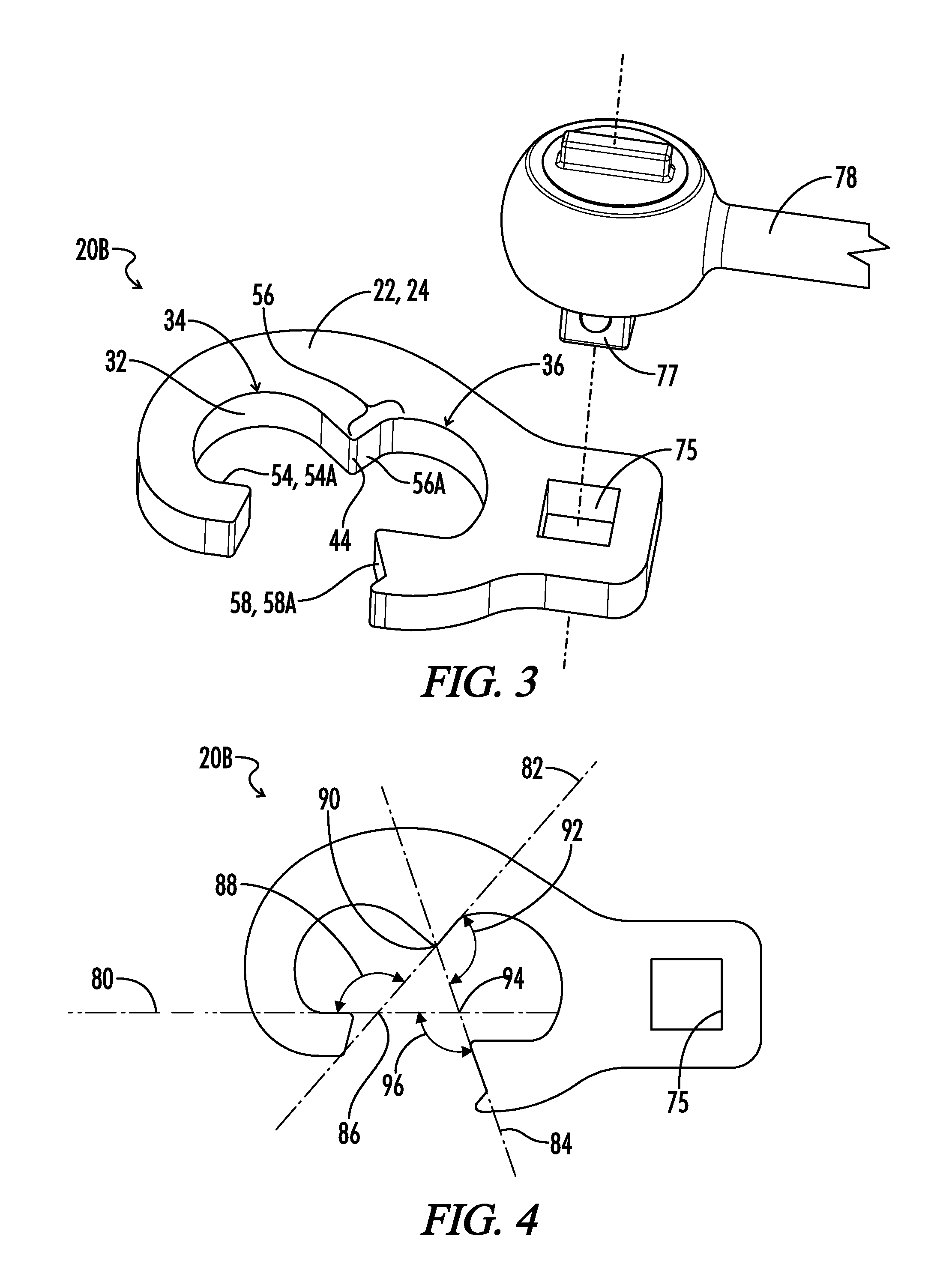
The patent is for a tool that can be used to tighten fence posts with a T-shape cross-section. The tool includes a driver body that is long and heavy, with one end attached to a wrench head. The wrench head has a space to fit around the T-shape cross-section without needing to remove wires from the fence post. The wrench head has surfaces that engage the fence post's center flange and its two side flanges, allowing for simultaneous tightening. This tool makes tightening fence posts faster and more efficient.

Problems solved by technology

One issue that is frequently encountered during the construction or maintenance of such fence systems is that the steel posts can become twisted about their cross-section either during installation or due to forces imposed during use.

Method used


Image

  • Fence Post Straightener
  • Fence Post Straightener
  • Fence Post Straightener

Examples


Embodiment Construction

Typical Studded T Post Dimensions

[0032]Referring now to FIGS. 6-8 a typical prior art T-shape cross-section steel fence post is shown and generally designated by the numeral 10. As best seen in FIGS. 7 and 8, the post 10 has a T-shape cross-section including a center flange 12 and first and second side flanges 14 and 16.

[0033]Protruding oppositely from the center flange 12 between the first and second side flanges 14 and 16 are a plurality of studs 18 spaced apart along the length of the fence post 10.

[0034]As best seen in FIGS. 7 and 8 the first and second side flanges 14 and 16 may have a slight curvature away from the center flange 12. Such a post 10 is generally referred to as a studded T post. As will be understood by those skilled in the art, such studded T posts 10 come in a variety of sizes typically defined by the weight of the post per foot of linear length of the post.

[0035]For example, the published dimensions for three different weights of studded T posts having the dim...


PUM


Abstract

A wrench apparatus is provided for applying torsion to a T-shape cross-section fence post. A wrench head has a lateral opening so that the wrench head can be placed laterally about the T-shape cross-section post. The wrench head includes first, second and third engagement surfaces arranged to simultaneously engage the three flanges of the fence post so that a torsional load can be simultaneously applied to all three flanges of the fence post.

Description

BACKGROUND OF THE INVENTION[0001]1. Field of the Invention[0002]A wrench apparatus is disclosed for applying torsion to a fence post having a T-shape cross-section including a center flange and two side flanges.[0003]2. Description of the Prior Art[0004]A common design for fencing used in the agricultural environment utilizes steel fence posts having a T-shape cross-section. The posts are typically driven into the ground using a heavy post driver that slides over the upper end of the post and is used to impact the upper end of the post to drive it into the ground. Several parallel strands of wire are then strung between adjacent posts to construct the fence.[0005]One issue that is frequently encountered during the construction or maintenance of such fence systems is that the steel posts can become twisted about their cross-section either during installation or due to forces imposed during use.[0006]There is a need for an efficient and effective wrench apparatus for engaging a twiste...

Claims


Application Information

Patent Timeline
IPC IPC(8): E04H17/26B25B13/08B25B13/50
CPCE04H17/261E04H17/263B25B13/08B25B13/50
Inventor KENNEMER, BRIANRAGER, TY
Owner TRACTOR SUPPLY COMPANY
Learn More