Control device for supercharging system

a control device and supercharging technology, applied in the direction of electric control, machines/engines, combustion engines, etc., can solve problems such as the breakage of various devices, and achieve the effects of suppressing the rapid fluctuation of the boost pressure, preventing the occurrence of surging in advance, and controlling the boost pressure quickly

Active Publication Date: 2016-10-20
MITSUBISHI HEAVY IND LTD
View PDF7 Cites 22 Cited by
  • Summary
  • Abstract
  • Description
  • Claims
  • Application Information

AI Technical Summary

Benefits of technology

[0040]According to at least one embodiment of the present invention, it is possible to provide a control device for a supercharging system capable of preventing occurrence of surging in advance while suppressing rapid fluctuation of a boost pressure, and of controlling the boost pressure quickly while avoiding an influence from communication delay.

Problems solved by technology

Such abnormal operation may lead to breakage of various devices, and thus needs to be prevented as much as possible.

Method used


Image

  • Control device for supercharging system
  • Control device for supercharging system
  • Control device for supercharging system

Examples


first embodiment

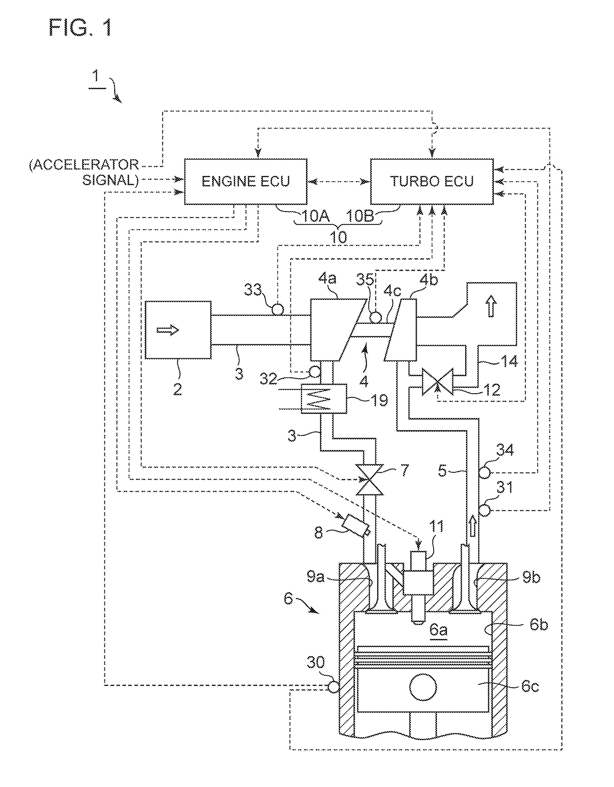
[0068]FIG. 1 is an overall configuration diagram of an engine system to which a control device of a supercharging system according to the first embodiment of the present invention is to be applied.

[0069]In the engine system 1 according to the present embodiment illustrated in FIG. 1, air (intake air) introduced into an intake duct 3 via an air cleaner 2 flows into a compressor 4a of a turbocharger 4 (supercharger). The turbocharger 4 includes a compressor 4a disposed in the intake duct 3, a turbine 4b disposed in an exhaust duct 5, and a rotor 4c coupling the compressor 4a and the turbine 4b. The turbine 4b is driven to rotate by exhaust energy of exhaust gas discharged from the engine 6, and thereby the compressor 4a is coaxially driven, so as to compress the intake air flowing into the compressor 4a.

[0070]The intake air compressed by the compressor 4a is cooled by an intercooler 19, and an intake amount of the intake air is adjusted by a throttle valve 7. The intake air is pre-mi...

second embodiment

[0110]FIG. 11 is an overall configuration diagram of an engine system to which a control device of a supercharging system according to the second embodiment of the present invention is to be applied. The engine system 1a of the present embodiment is basically similar to the embodiment illustrated in FIG. 1 in terms of configuration, except that the engine system 1a does not include the bypass channel 14 and the waste-gate valve 12. Thus, the same component is associated with the same reference numeral and not described in detail.

[0111]In the present embodiment, as illustrated in FIG. 11, the turbocharger 4 is a variable turbocharger including the turbine 4b driven to rotate by exhaust energy of exhaust gas discharged from the engine 6, the compressor 4a driven coaxially with the turbine 4b, and a variable control mechanism 4d for controlling a flow of exhaust gas that flows into the turbine 4b. The variable control mechanism 4d is adjusted to control a flow of exhaust gas flowing in...

third embodiment

[0114]FIG. 12 is an overall configuration diagram of an engine system to which a control system of a supercharging system according to the third embodiment of the present invention is to be applied. The engine system 1b of the present embodiment is basically similar to the embodiment illustrated in FIG. 1 in terms of configuration, except for the two-stage turbo-charging system including two turbochargers, a high-pressure stage turbocharger 4A and a low-pressure stage turbocharger 4B. Thus, the same component is associated with the same reference numeral and not described in detail.

[0115]In the present embodiment, as illustrated in FIG. 12, the supercharger for compressing intake air to be supplied to the engine 6 includes the high-pressure stage turbocharger 4A and the low-pressure stage turbocharger 4B. The high-pressure stage turbocharger 4A includes a high-pressure stage turbine 4Ab disposed in the exhaust duct 5 of the engine 6 and driven to rotate by exhaust energy from the en...


PUM


Abstract

A control device (10) for a supercharging system for supplying compressed intake air to an engine (6) includes: an engine controller (10A) including an engine signal input part (10A1) and an engine control part (10A2) configured to control an operational state of the engine and to compute a target boost pressure of a supercharger (4); and a turbo controller (10B2) including a turbo signal input part (10B1) and a turbo control part (10B2) configured to compute a margin of the supercharger. The control device is configured to compute a target boost-pressure corrected value by correcting the target boost pressure in accordance with a magnitude of the margin computed by the turbo control part, and to control a boost-pressure control unit (12) so that the boost pressure of the supercharger reaches the target boost-pressure corrected value.

Description

TECHNICAL FIELD[0001]The present disclosure relates to a control device for a supercharging system for supplying compressed intake air to an engine.BACKGROUND ART[0002]As a technique to improve an output of an engine, a method (supercharging) of compressing intake air with a supercharger and supplying an engine with the compressed intake air is known, and widely used in an engine for an automobile and the like. A supercharger may transitionally enter an abnormal operational state with surging, over-speed, or the like, depending on the operational state of the supercharger. Such abnormal operation may lead to breakage of various devices, and thus needs to be prevented as much as possible.[0003]Patent Document 1 discloses an invention, as a control device for a turbocharger, for suppressing surging by predicting occurrence of surging from an operational state of the turbocharger and opening a waste-gate valve immediately before occurrence of surging to reduce a flow rate of exhaust ga...

Claims


Application Information

Patent Timeline
Patent Type & Authority Applications(United States)
IPC IPC(8): F02D41/00F02B37/04F02D41/30F02D41/14F02B37/12F02B37/013F02B37/18
CPCF02D41/0007F02B37/013F02B37/04F02B37/18F02B2037/122F02B37/12F02D41/30F02B2037/125F02D41/1446F02B2039/168F02D41/1401F02D41/32F02D2041/141F02D2200/0406Y02T10/12
Inventor SASE, RYOYAMASHITA, YUKIOTAKAYANAGI, KOMATSUO, ATSUSHIHAYASHI, RIKIKAZU
Owner MITSUBISHI HEAVY IND LTD
Why Eureka
Try Eureka