Electro-Optic Grating-Coupled Surface Plasmon Resonance (EOSPR)

a technology of plasmon resonance and optical grating, which is applied in the field of electrooptic gratingcoupled surface plasmon resonance (eospr), can solve the problems of low sensitivity of classic approaches to limitation of the application of this technology to environmental and clinical samples, and low sensitivity of spr as compared to labeled techniques like elisa, etc., to achiev

Active Publication Date: 2016-10-27
CIENCIA
View PDF0 Cites 5 Cited by
  • Summary
  • Abstract
  • Description
  • Claims
  • Application Information

AI Technical Summary

Benefits of technology

The patent describes a new sensor platform that can capture and detect specific cells or molecules on the surface of a special chip. This chip uses surface plasmon resonance and / or surface plasmon coupled emission analysis to detect small amounts of samples. The platform includes a chip with an integrated or standalone detection apparatus. The chip is designed to have a fluid-tight enclosure called a flow chamber that can be used to introduce and retain samples. The chip is also polished to create an optimal surface for detecting small amounts of light. The patent also explains the process of depositing a conductive layer, a grating-embossed or patterned electro-optic polymer, and a thin gold layer on the chip. The software-controlled voltage generator allows for the precise control of the optics, fluidics, and voltage. Overall, the patent presents a detailed description and technical effects of the new sensor platform that can detect specific cells or molecules with high accuracy.

Problems solved by technology

Alas, SPR has not proven sensitive enough to detect trace quantities of small molecules, particularly in complex media, and the low sensitivity of classic approaches to SPR as compared to labeled techniques like ELISA has proven to be a limitation to the application of this technology to environmental and clinical samples.
Limitations of the Kretschmann configuration include instrument size, instrument price, ease of use, and the relatively small number of simultaneous analyses that can be performed.
While GCSPR systems offer considerable improvement over the limitations of Kretschmann systems, they remain less sensitive than fluorescent techniques, and the dependence on moving parts for angle scanning makes these instruments relatively fragile and therefore ill-suited for field use.

Method used


Image

  • Electro-Optic Grating-Coupled Surface Plasmon Resonance (EOSPR)
  • Electro-Optic Grating-Coupled Surface Plasmon Resonance (EOSPR)
  • Electro-Optic Grating-Coupled Surface Plasmon Resonance (EOSPR)

Examples


Embodiment Construction

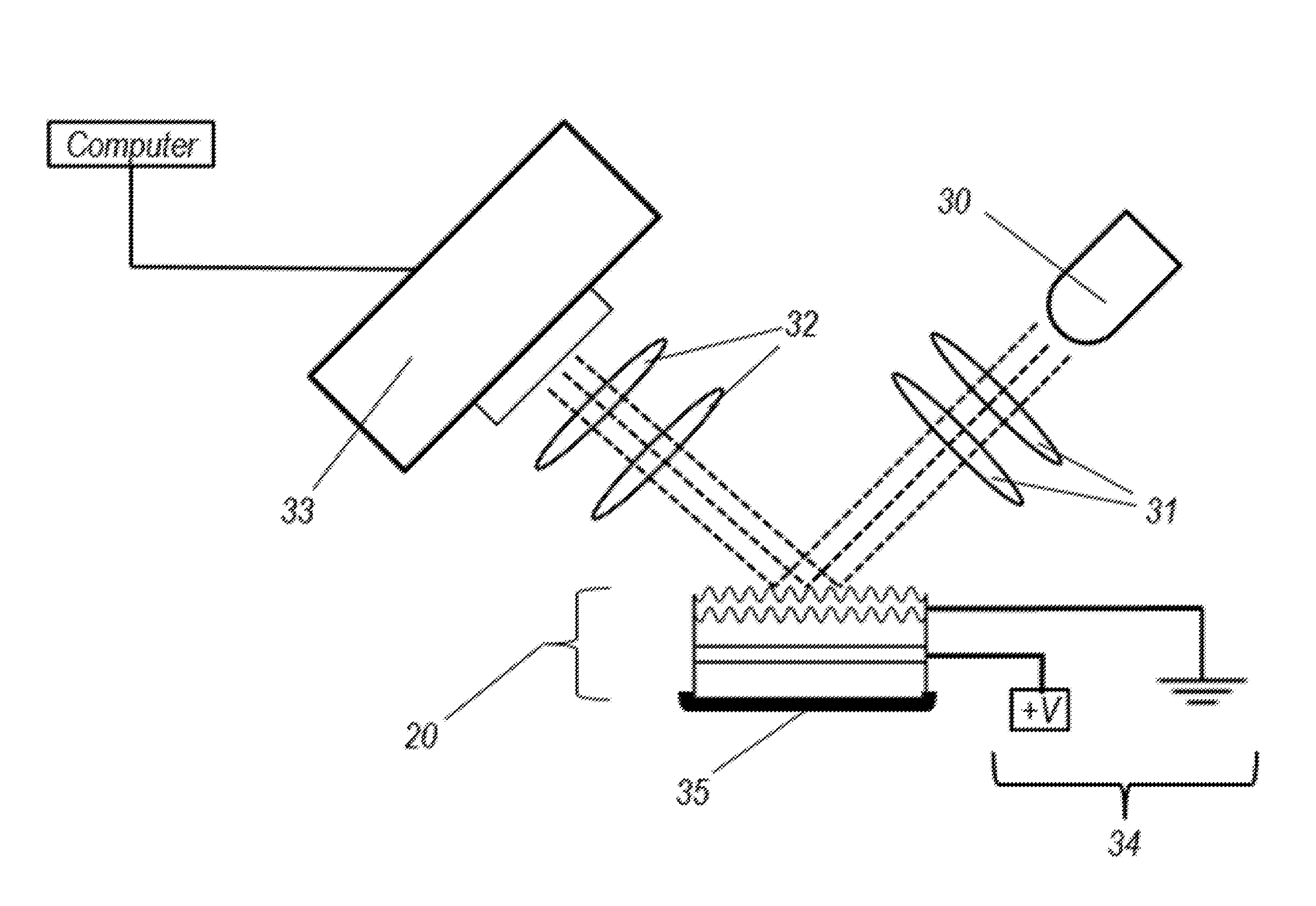
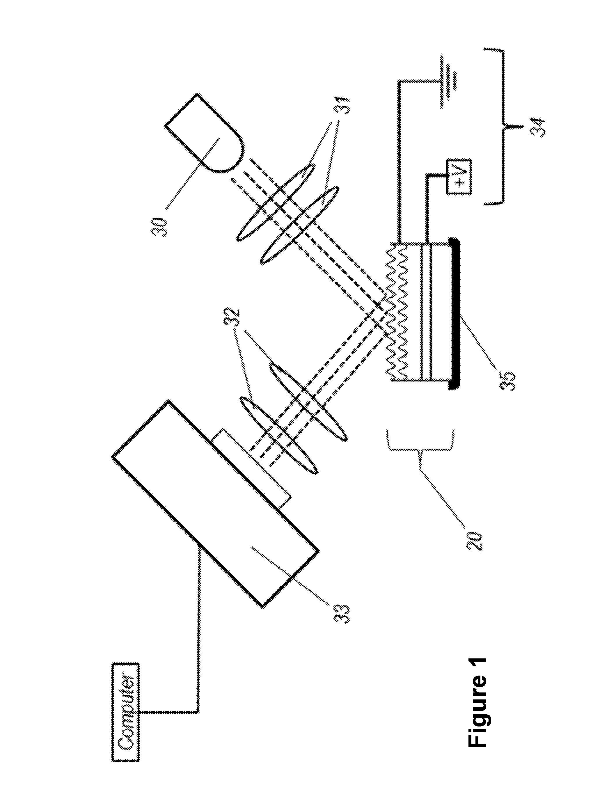
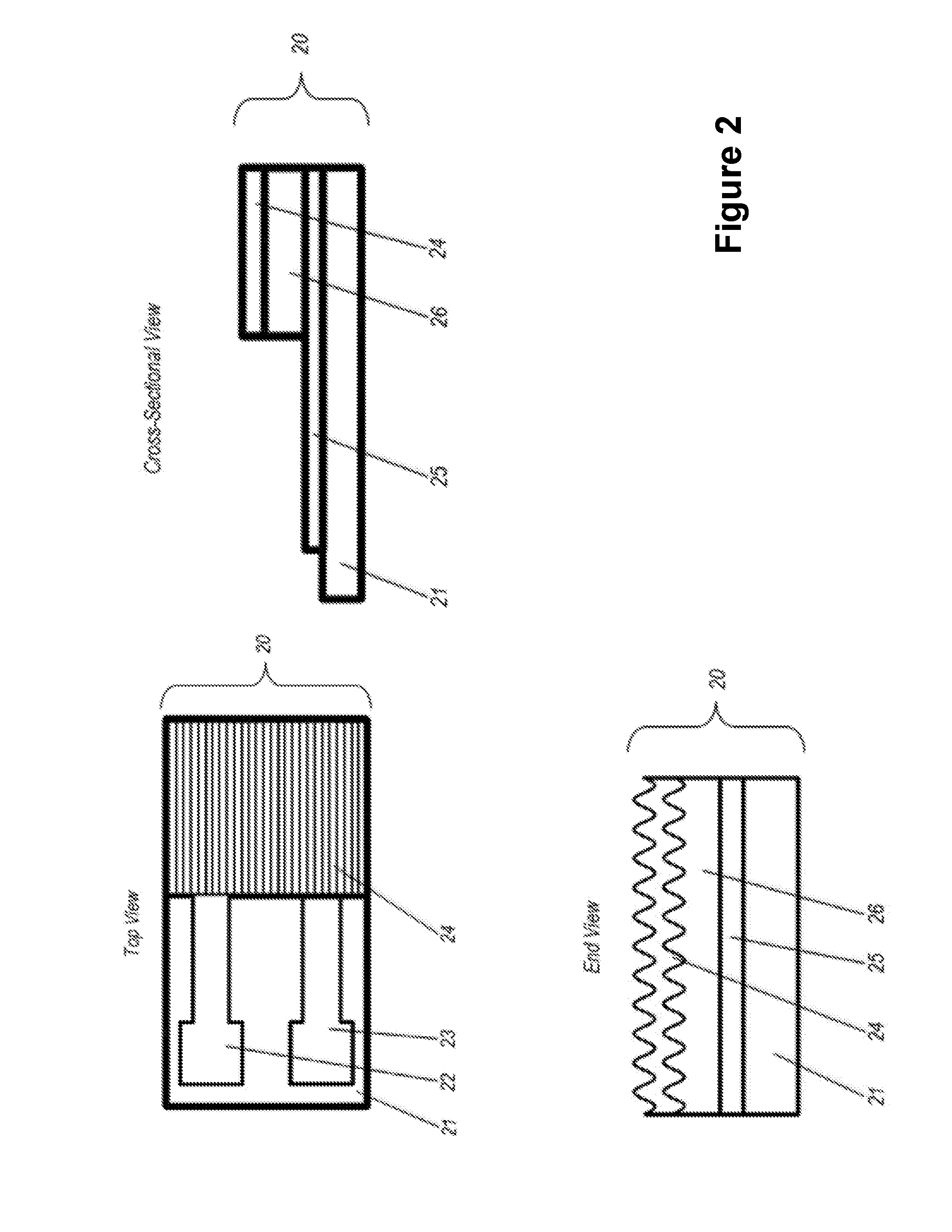
[0019]As used herein, the term “electro-optic polymer” or “EO polymer” refers to polymers or other materials whose dielectric constant varies as a function of applied voltage. SEO100 from Soluxra, LLC of Seattle, Wash.is an example of an electro-optic polymer potentially compatible with the disclosed embodiments. The acronym GCSPR stands for Grating-Coupled Surface Plasmon Resonance, and EOSPR stands for Electro-Optic grating-coupled Surface Plasmon Resonance. SPCE stands for Surface Plasmon Coupled Emission. The EOSPR sensor surface is alternatively called the “chip,” the “sensor chip,” or the “EOSPR chip,” and will support an electro-optic grating-coupled approach to both SPR and SPCE.

[0020]An EOSPR sensor chip and complementary detection schema providing surface plasmon resonance analysis with or without concomitant SPCE measurements are described below.

[0021]In a dielectric-metal-dielectric arrangement, Equation 1 holds true, and Ksp therefore depends on the dielectric constant ...


PUM


Abstract

An instrument for measuring and analyzing surface plasmon resonance (SPR) and / or surface plasmon coupled emission on an electro-optic grating-coupled sensor surface is described herein. The sensor chip achieves SPR through a grating-coupled approach, with variations in the local dielectric constant at regions of interest (ROI) at the sensor surface detected as a function of the intensity of light reflecting from these ROI. Unlike other grating-based approaches, the metal surface is sufficiently thin that resonant conditions are sensitive to dielectric constant changes both above and below the metal surface (like the Kretschmann configuration). Dielectric constant shifts that occur as mass accumulates on the surface can be returned to reference intensities by applying voltage across the underlying electro-optic polymer. Approaches to the development of the sensor surfaces are described, as are software and hardware features facilitating sample handling, data gathering, and data analysis by this solid-state approach.

Description

CROSS-REFERENCE TO RELATED APPLICATIONS[0001]This application is a continuation of U.S. patent application Ser. No. 14 / 534,511, filed Nov. 6, 2014, for “Electro-Optic Grating-Coupled Surface Plasmon Resonance (EOSPR),” which claims the benefit of U.S. Provisional Patent Application No. 61 / 900,548, filed Nov. 6, 2013, the entire contents of each of which are hereby incorporated by reference.STATEMENT REGARDING FEDERALLY SPONSORED RESEARCH OR DEVELOPMENT[0002]This application is based on research and development done under NIH / NIGMS Grant No. 1R43GM104636-01.TECHNOLOGICAL FIELD[0003]The described embodiments relate to an instrument and method for the detection, measurement, and characterization of a wide variety of specific molecules, simple or complex solutions, and biological cells.BACKGROUND OF THE INVENTION[0004]Requirements for the identification and measurement of biological or chemical entities in a sample typically include a means of isolating or separating the analyte in ques...

Claims


Application Information

Patent Timeline
Patent Type & Authority Applications(United States)
IPC IPC(8): G01N21/552
CPCG02F1/195G01N21/553G01N21/7743G01N2201/067G02F1/061
Inventor PAGE, WILLIAMGIBSON, GEORGE N.GUIGNON, ERNEST F.
Owner CIENCIA
Why Eureka
Try Eureka