
Hierarchical optimization for processing objectives sequentially and/or iteratively

a technology of processing objectives and optimization, applied in the field of hierarchy optimization for processing objectives, can solve problems such as non-linear computation, complex and regulated objectives, and constraints on values

Active Publication Date: 2022-01-13
INTUIT INC
View PDF0 Cites 0 Cited by
  • Summary
  • Abstract
  • Description
  • Claims
  • Application Information

AI Technical Summary

Benefits of technology

The patent describes a system and technique for optimizing objectives, such as minimizing tax liability and maximizing retirement contributions. The system uses a hierarchical approach to reduce the search space for optimizers and generate an optimal solution in a short amount of time. The system includes evaluators that can execute objective functions in their native format and syntax. The technical effects of the patent include improved efficiency and speed in optimizing objectives and reducing computing resources.

Problems solved by technology

Further, such objectives may be complex and regulated by multiple regulations.
Additionally, the regulations may cause such objectives to be expressed in non-linear mathematical expressions and may constrain the values of the variables and / or the results of the objectives by non-linear constraints.
Therefore, solving such objectives may require non-linear computations.
However, non-linear computations of such objectives using existing systems and techniques may consume a significant amount of computing resources (e.g., processor cycles), and may require time such that it would not be feasible in multiple practical scenarios.
However, existing optimizers may not be capable to accurately optimize non-linear mathematical expressions within a feasible amount of time.
Therefore, existing optimizers may fail to provide results that the customers are seeking.
However, existing systems may be hard-coded for specific objectives and / or solutions.
Therefore, such rigidity of existing systems may not allow the various combinations of different objectives for the different customers or it may be highly inefficient to use the existing systems and techniques to combine the different objectives of the customers.

Method used


Image

  • Hierarchical optimization for processing objectives sequentially and/or iteratively
  • Hierarchical optimization for processing objectives sequentially and/or iteratively
  • Hierarchical optimization for processing objectives sequentially and/or iteratively

Examples


example hierarchical

Optimization System

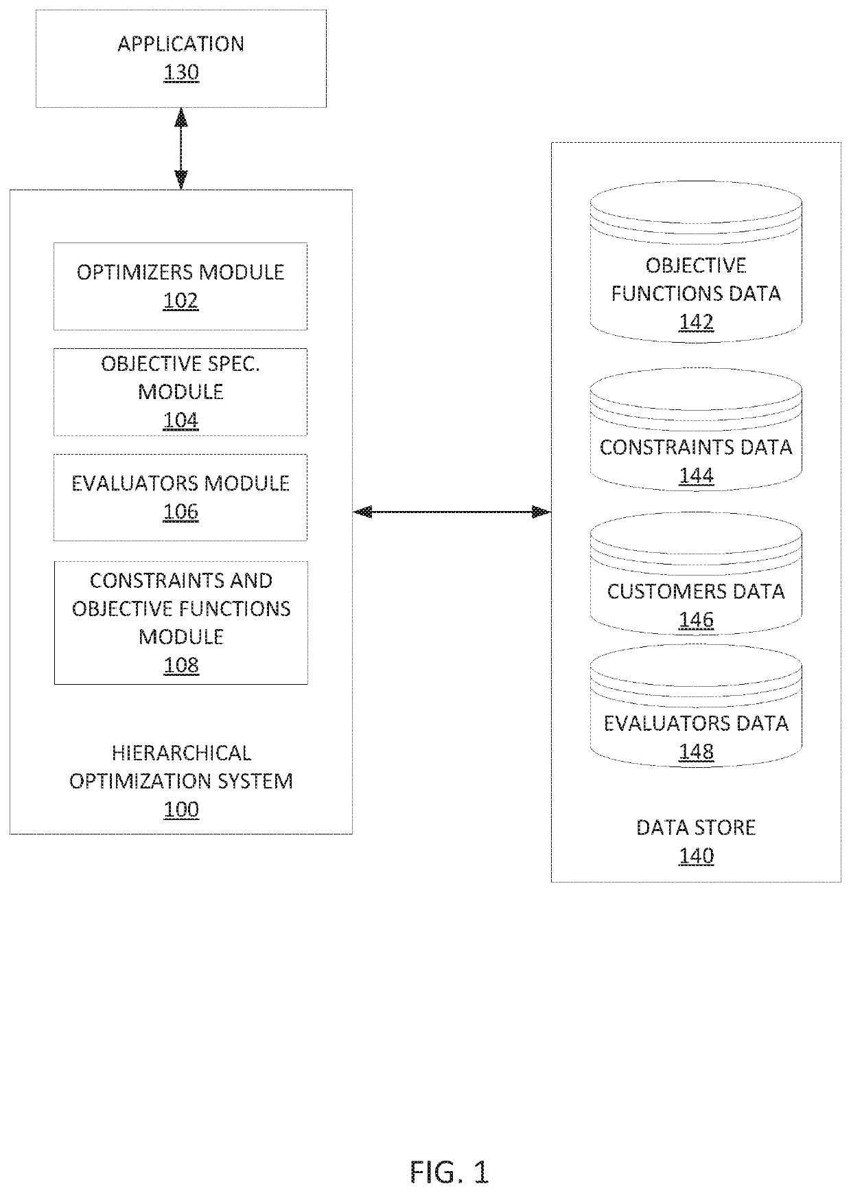
[0029]FIG. 1 depicts an example hierarchical optimization system 100 for optimizing one or more primary objectives. As shown in FIG. 1, the hierarchical optimization system 100 may be communicatively coupled to an application 130, and a data store 140. The hierarchical optimization system 100 includes optimizers module 102, objective specifications module 104, evaluators module 106, constraints and objective functions module 108.

[0030]The optimizers module 102 may include one or more optimizers 112a, 112b, . . . , 112n, collectively referred to as optimizers 112, which are configured to determine the optimal values for the variable inputs of a sub-objective. Examples of the one or more optimizers 112 may include, but are not limited to, simplicial homology global optimisation (SHGO) optimizers, sequential least squares quadratic programming (SLSQP) optimizers, linear programming (LinProg) optimizers, and the like. In some implementations, each optimizer 112 may be...

example method

of Hierarchical Optimization for Processing Objectives Sequentially And / Or Iteratively

[0062]FIG. 4 depicts an example method 400 of hierarchical optimization of processing objectives sequentially and / or iteratively.

[0063]Method 400 begins at step 402 with receiving a request to optimize a primary objective from a requestor.

[0064]In some implementations, the request to optimize a primary objective may include an identifier associated with the primary objective. In some implementations, the requestor may be an application (e.g., application 130) communicatively coupled to a hierarchical optimization system (e.g., the hierarchical optimization system 100).

[0065]Method 400 then proceeds to step 404 with determining, based on the request, an ordered set of stages to optimize the primary objective.

[0066]As described above, an ordered set of stages to optimize the primary objective may be provided by a user (e.g., domain expert), and the ordered set of stages is a sequence in which the sta...

example processing

System

[0078]FIG. 5 depicts an exemplary processing system 500 configured to perform methods for hierarchical optimization of processing objectives sequentially and / or iteratively.

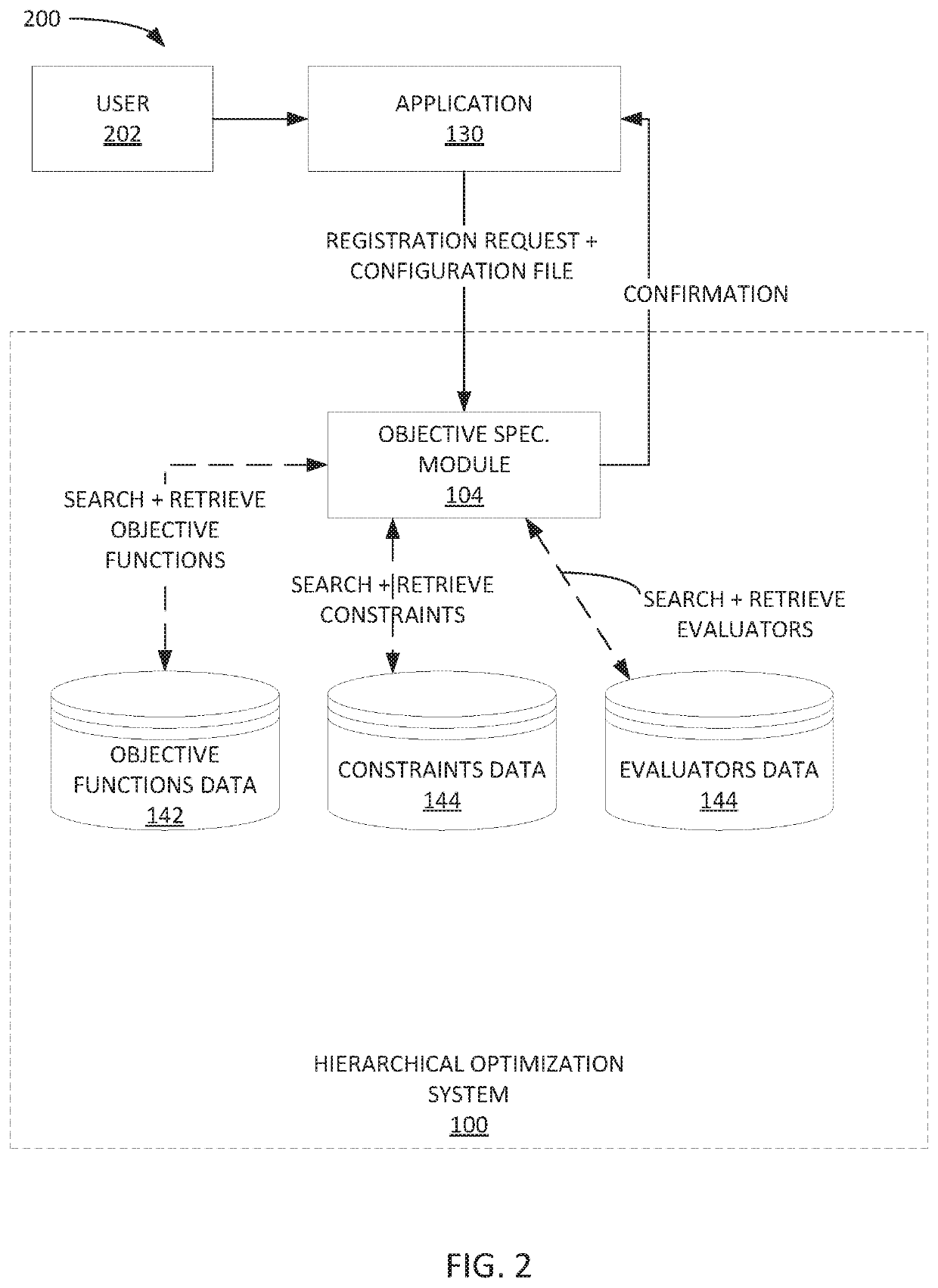
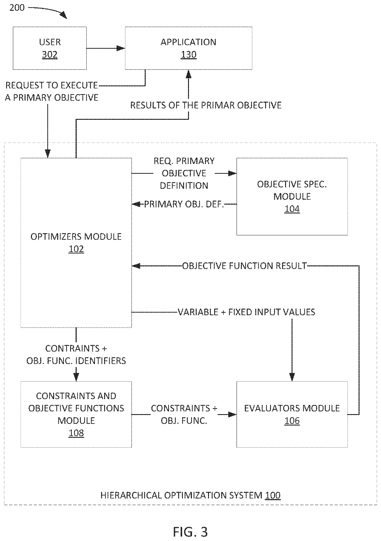
[0079]Processing system 500 includes a CPU 502 connected to a data bus 508. CPU 502 is configured to process computer-executable instructions, e.g., stored in memory 510 or storage 530, and to cause processing system 500 to perform methods as described herein, for example with respect to FIGS. 2-4. CPU 502 is included to be representative of a single CPU, multiple CPUs, a single CPU having multiple processing cores, and other forms of processing architecture capable of executing computer-executable instructions.

[0080]Processing system 500 further includes input / output devices and interface 504, which allows processing system 500 to interface with input / output devices, such as, for example, keyboards, displays, mouse devices, pen input, touch sensitive input devices, cameras, microphones, and other devices t...


PUM


Abstract

Certain aspects of the present disclosure provide techniques for hierarchical optimization including: receiving a request to optimize a primary objective; determining a set of stages to optimize the primary objective; for each respective stage of the set of stages: determining an objective function; when the respective stage is the first stage to be processed: determining values of a set of variable inputs to the respective stage and an output of the objective function; when the respective stage is not the first stage: updating a set of fixed inputs to the respective stage by including the variable inputs to one or more previously processed stages and their corresponding values to the set of fixed inputs to the respective stage; determining values of the set of variable inputs to the respective stage and output of the objective function for the respective stage; providing a final output for display on a display device.

Description

INTRODUCTION[0001]Aspects of the present disclosure relate to computationally efficient systems and methods for hierarchical optimization for processing objectives sequentially and / or iteratively.[0002]Generally, problems or objectives that financial institutions (e.g., tax agencies, financial planning agencies, and the like) are asked to resolve by their customers vary from one customer to another customer due to the different circumstances of the customers. Further, such objectives may be complex and regulated by multiple regulations. An example of such an objective is to minimize tax liability. Resolving such objectives may require calculating values of a large number of variables. Additionally, the regulations may cause such objectives to be expressed in non-linear mathematical expressions and may constrain the values of the variables and / or the results of the objectives by non-linear constraints.[0003]Therefore, solving such objectives may require non-linear computations. Howev...

Claims


Application Information

Patent Timeline
Patent Type & Authority Applications(United States)
IPC IPC(8): G06Q10/06G06Q30/00G06Q10/04G06N5/04
CPCG06Q10/06316G06Q30/016G06Q40/10G06N5/04G06Q10/04G06Q40/06G06Q40/02
Inventor AGARWAL, SUDHIRSANFORD, II, ROLAND ALLEN
Owner INTUIT INC
Learn More